Gigabyte GA-6LASL Manual
Gigabyte GA-6LASL Manual
 |
View all Gigabyte GA-6LASL manuals
Add to My Manuals
Save this manual to your list of manuals |
Gigabyte GA-6LASL manual content summary:
- Gigabyte GA-6LASL | Manual - Page 1
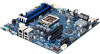
GA-6LASH GA-6LASL LGA1150 socket motherboard for Intel® E3 series processors User's Manual Rev. 1001 - Gigabyte GA-6LASL | Manual - Page 2
respective owners. Disclaimer Information in this manual is protected by copyright laws and is the property of GIGABYTE. Changes to the specifications and features in this manual may be made by GIGABYTE without prior notice. No part of this manual may be reproduced, copied, translated, transmitted - Gigabyte GA-6LASL | Manual - Page 3
Table of Contents Box Contents...5 GA-6LASH/GA-6LASL Motherboard Layout 6 GA-6LASH Block Diagram 9 GA-6LASL Block Diagram 10 Chapter 1 Hardware 20 1-6 Internal Connectors 21 Chapter 2 BIOS Setup 36 2-1 The Main Menu 38 2-2 Advanced Menu 40 2-2-1 ACPI Configuration 41 2-2-2 Trusted - Gigabyte GA-6LASL | Manual - Page 4
Services 80 2-4 Security Menu 81 2-4-1 Secure Boot menu 82 2-4-1-1 Image Execution Policy 83 2-4-1-2 Key Management 84 2-5 Server Management Menu (GA-6LASH Only 86 2-5-1 BMC LAN Configuration (GA-6LASH Only 87 2-5-2 View FRU Information (GA-6LASH Only 88 2-5-3 System Event Log (GA-6LASH - Gigabyte GA-6LASL | Manual - Page 5
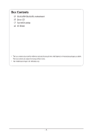
Box Contents GA-6LASH/GA-6LASL motherboard Driver CD Two SATA cables I/O Shield • The box contents above are for reference only and the actual items shall depend on the product package - Gigabyte GA-6LASL | Manual - Page 6
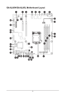
GA-6LASH/GA-6LASL Motherboard Layout 1 23 45 6 7 8 42 43 44 9 10 41 40 39 38 37 19 36 20 35 21 34 22 31 30 29 28 27 18 33 32 25 23 26 24 11 13 12 14 15 16 17 - 6 - - Gigabyte GA-6LASL | Manual - Page 7
slot Audio connectors LAN1 port (top/NCSI LAN port for server management) / USB 2.0 ports (bottom) LAN2 port ( DIMM slot (channel 1 slot 0 ) 24 pin main power connector Intel LGA1150 socket CPU fan connector SATA connectors SATA port 1 DOM support jumper SATA port 0 DOM support jumper USB 2.0 Type - Gigabyte GA-6LASL | Manual - Page 8
plane board header TPM module connector Serial port cable connector Case open intrusion header SPDIF In header NOTE! This feature/device is only for GA-6LASH. CAUTION! If a SATA type hard drive is connected to the motherboard, please ensure the jumper is closed and set to 2-3 pins (Default setting - Gigabyte GA-6LASL | Manual - Page 9
GA-6LASH Block Diagram - 9 - Micro ATX (9.6" x 9.6") NCP81161 PCIe x16 SLOT SLOT3 /s BLACKBLUE BLACKBLUE 6x SATA (2x 6Gb/s SATA + 4x 3Gb/s SATA for SATA_DOM, SW RAID0/1/5) PCH Lynx Point (SERVER SKU_C222) SATA0 SATA1 SATA2 SATA3 SATA4 SATA5 9x USB2.0 + 2 USB3.0 USB TYPE A PCIe2(x1) 1 GB/s - Gigabyte GA-6LASL | Manual - Page 10
GA-6LASL Block Diagram - 10 - Micro ATX (9.6" x 9.6") NCP81161 PCIe x16 SLOT 4GB/s BLACKBLUE BLACKBLUE 6x SATA (2x 6Gb/s SATA + 4x 3Gb/s SATA for SATA_DOM, SW RAID0/1/5) PCH Lynx Point (SERVER SKU_C222) SATA0 SATA1 SATA2 SATA3 SATA4 SATA5 9x USB2.0 + 2 USB3.0 USB TYPE A PCIe2(x1) 1 GB/s - Gigabyte GA-6LASL | Manual - Page 11
electrostatic discharge (ESD). Prior to installation, carefully read the user's manual and follow these procedures: • Prior to installation, do not remove are uncertain about any installation steps or have a problem related to the use of the product, please consult a certified computer technician. - Gigabyte GA-6LASL | Manual - Page 12
supports 128MB VRAM (GA-6LASH) ASPEED® AST1300 supports 128MB VRAM (GA-6LASL) 4 x SATA 3Gb/s connectors 2 x SATA 6Gb/s connectors Support ) 1 x PCI Express x4 slot, running at x1 (Gen2/PCIE_1) 1 x 24-pin ATX main power connector 1 x 8-pin ATX 12V power connector 4 x SATA 3Gb/s connectors 2 x SATA - Gigabyte GA-6LASL | Manual - Page 13
ASPEED® AST2300 chip (GA-6LASH) ŠŠ ASPEED® AST1300 chip (GA-6LASL) ŠŠ System voltage supported will depend on the CPU/system cooler you install. ŠŠ 1 x 128 Mbit flash ŠŠ AMI BIOS ŠŠ Micro ATX Form Factor; 9.6 inch x 9.6 inch, 4 Layers NOTE! This feature/device is only for GA-6LASH. GIGABYTE - Gigabyte GA-6LASL | Manual - Page 14
1-3 Installing the CPU and CPU Cooler Read the following guidelines before you begin to install the CPU: • Make sure that the motherboard supports the CPU. • Always turn off the computer and unplug the power cord from the power outlet before installing the CPU to prevent hardware damage. • Locate - Gigabyte GA-6LASL | Manual - Page 15
B. Follow the steps below to correctly install the CPU into the motherboard CPU socket. Before installing the CPU, make sure to turn off the computer and unplug the power cord from the power outlet power plug to prevent any damage to prevent damage to the CPU. Step 1: Gently press the CPU socket - Gigabyte GA-6LASL | Manual - Page 16
" when pushing down each push pin. Check that the Male and Female push pins are joined closely. (Refer to your CPU cooler installation manual for instructions on installing the cooler.) Step 5: After the installation, check the back of the motherboard. If the push pin is inserted as the picture - Gigabyte GA-6LASL | Manual - Page 17
unable to insert the memory, switch the direction. 1-4-1 Dual Channel Memory Configuration This motherboard provides four DDR3 memory sockets and supports Dual Channel Technology. When the memory is installed, the BIOS will automatically detect the specifications and capacity of the memory. Enabling - Gigabyte GA-6LASL | Manual - Page 18
1-4-2 Installing a Memory Before installing a memory module, make sure to turn off the computer and unplug the power cord from the power outlet to prevent damage to the memory module. Be sure to install DDR3 DIMMs on this motherboard. Installation Step: Step 1. Insert the DIMM memory module - Gigabyte GA-6LASL | Manual - Page 19
port provides Internet connection at up to 1 Gbps data rate. The following describes the states of the LAN port LEDs. USB 2.0/1.1 Port The USB port supports the USB 2.0/1.1 specification. Use this port for USB devices such as a USB keyboard/mouse, USB printer, USB flash drive and etc. Line In Jack - Gigabyte GA-6LASL | Manual - Page 20
) 22) SATA_SGPIO 23) BAT 24) CLR_CMOS 25) BIOS_RCVR 26) PCH_ME 27) BIOS_PWD 28) ME_UPDATE 29) CASE_OPEN 30) SPDIF NOTE! This feature/device is only for GA-6LASH. Hardware Installation - 21 - - Gigabyte GA-6LASL | Manual - Page 21
Read the following guidelines before connecting external devices: • First make sure your devices are compliant with the connectors you wish to connect. • Before installing the devices, be sure to turn off the devices and your computer. Unplug the power cord from the power outlet to prevent damage to - Gigabyte GA-6LASL | Manual - Page 22
. The power connector possesses a foolproof design. Connect the power supply cable to the power connector in the correct orientation. The 12V power connector mainly supplies power to the CPU. If the 12V power connector is not connected, the computer will not start. To meet expansion requirements, it - Gigabyte GA-6LASL | Manual - Page 23
design. When connecting a fan cable, be sure to connect it in the correct orientation (the black connector wire is the ground wire). The motherboard supports CPU fan speed control, which requires the use of a CPU fan with fan speed control design. For optimum heat dissipation, it is recommended that - Gigabyte GA-6LASL | Manual - Page 24
/s Connectors) The SATA connectors conform to SATA 6Gb/s standard and are compatible with SATA 3Gb/s and 1.5Gb/s standard. Each SATA connector supports a single SATA device. 1 1 SATA0 SATA1 SATA0 SATA1 7 7 When SATA_DOM0/1 jumper are set to 1-2 pin: Pin No. Definition 1 GND 2 TXP 3 TXN 4 GND - Gigabyte GA-6LASL | Manual - Page 25
(SATA 3Gb/s Connectors) The SATA connectors conform to SATA 3Gb/s standard and are compatible with SATA 1.5Gb/s standard. Each SATA connector supports a single SATA device. SATA23 SATA45 7 1 7 1 Pin No. 1 2 3 4 5 6 7 Definition GND TXP TXN GND RXN RXP GND 14) IPMB (IPMB connector) 1 Pin No - Gigabyte GA-6LASL | Manual - Page 26
15) F_USB3 (USB 3.0 Header) The headers conform to USB 3.0 specification. Each USB header can provide two USB ports via an optional USB bracket. For purchasing the optional USB bracket, please contact the local dealer. G.QBOFM Pin No. Definition 1 Power 20 1 2 IntA_P1_SSRX- 3 IntA_P1_SSRX+ 4 - Gigabyte GA-6LASL | Manual - Page 27
17) COM2 (Serial Port Header) The COM header can provide one serial port via an optional COM port cable. For purchasing the optional COM port cable, please contact the local dealer. Pin No. Definition 12 1 NDCD- 2 NSIN 3 NSOUT 4 NDTR- 5 GND 6 NDSR- 9 10 7 NRTS- 8 NCTS- 9 NRI- 10 No Pin - Gigabyte GA-6LASL | Manual - Page 28
active LED Signal NMI switch Signal cathode(-) LAN1 Link LED Signal cathode(-) The front panel design may differ by chassis. A front panel module mainly consists of power switch, reset switch, power LED, hard drive activity LED, speaker and etc. When connecting your chassis front panel module to - Gigabyte GA-6LASL | Manual - Page 29
19 P_3V3_AUX 20 BP_HDD_TYPE 21 P_3V3_AUX 22 FAN_TYPE 23 GND 24 KEY 25 BP_PRESENSE 26 GND 21) BMC_LED (BMC Firmware Readiness LED/GA-6LASH Only) State Description On BMC firmware is initial Blinking BMC firmware is ready Off System is powered off - 30 - Hardware Installation - Gigabyte GA-6LASL | Manual - Page 30
the 4 signals, 3 are driven by the HBA and 1 is driven by the backplane. Typically, the HBA is a storage controller located inside a server, desktop, rack or workstation computer that interfaces with Hard disk drives (HDDs) to store and retrieve data. 2 8 1 7 Pin No. 1 2 3 4 5 6 7 8 Definition - Gigabyte GA-6LASL | Manual - Page 31
to the motherboard. • After system restart, go to BIOS Setup Exit menu and load factory defaults (select Load Default Values) or manually configure the BIOS settings (refer to Chapter 2, "BIOS Setup," for BIOS configurations). 25) BIOS_RCVR (BIOS Recovery Jumper) 1 1-2 Close: Normal operation - Gigabyte GA-6LASL | Manual - Page 32
26) PCH_ME/ME_UPDATE (ME Recover Jumpers) 1 1-2 Close: Normal operation (Default setting) 1 2-3 Close: ME recovery mode. 27) BIOS_PWD (Clearing Supervisor Password Jumper) 1 1-2 Close: Normal operation. (Default setting) 1 2-3 Close: Clear supervisor password. Hardware Installation - 33 - - Gigabyte GA-6LASL | Manual - Page 33
28) ME_UPDATE (ME Recover Jumpers) 1-2 Close: Normal operation (Default setting) 1 2-3 Close: ME update. 1 29) CASE_OPEN (Case open intrusion header) Open: Normal operation. Closed: Active chassis intrustion alert. - 34 - Hardware Installation - Gigabyte GA-6LASL | Manual - Page 34
30) SPDIF_IN (SPDIF In header) 1 2 Pin No. 1 2 Definition GND SPDIF_IN - 35 - Hardware Installation - Gigabyte GA-6LASL | Manual - Page 35
is turned on. • BIOS flashing is potentially risky, if you do not encounter problems of using the current BIOS version, it is recommended that you don't flash the changes Execute command or enter the submenu Main Menu: Exit the BIOS Setup program Submenus: Exit current - Gigabyte GA-6LASL | Manual - Page 36
Main This setup page includes all the items in standard compatible BIOS. password only allows you to view the BIOS settings but not to make changes. Server Management (GA-6LASH Only) Server additional features enabled/disabled setup menus. Event Logs This setup page provides items for - Gigabyte GA-6LASL | Manual - Page 37
keys to move among the items and press to accept or enter other sub-menu. Main Menu Help The on-screen description of a highlighted setup option is displayed on the bottom line of the Main Menu. Submenu Help While in a submenu, press to display a help screen (General Help) of function - Gigabyte GA-6LASL | Manual - Page 38
BIOS Information BIOS Version Display version number of the BIOS setup utility. BIOS Build Date and Time Displays the date and time when the BIOS setup utility was created. BMC Information BMC Firmware Version Display version number of the BMC setup utility. SDR Version Display the SDR version of - Gigabyte GA-6LASL | Manual - Page 39
2-2 Advanced Menu The Advanced menu display submenu options for configuring the function of various hardware components. Select a submenu item, then press Enter to access the related submenu screen. GA-6LASH GA-6LASL BIOS Setup - 40 - - Gigabyte GA-6LASL | Manual - Page 40
2-2-1 ACPI Configuration ACPI Settings ACPI Sleep State Select the highest ACPI sleep state the system will enter, when the suspend button is pressed. Options available: Suspend Disabled/S1 only (CPU Stop Clock)/S3 only (Suspend to RAM)/ Both S1 and S3 available for OS to choose from. Default - Gigabyte GA-6LASL | Manual - Page 41
2-2-2 Trusted Computing (Optional) Configuration Security Device Support Select Enabled to activate TPM support feature. Options available: Enabled/Disabled. Default setting is Enabled. Current Status Information Display current TPM status information. BIOS Setup - 42 - - Gigabyte GA-6LASL | Manual - Page 42
2-2-3 PCI Subsystem Settings PCI Express Slot #1/2/3 I/O ROM When enabled, This setting will initialize the device expansion ROM for the related PCI-E slot. Options available: Enabled/Disabled. Default setting is Enabled. Onboard LAN #1 I/O ROM Configure onboard LAN devices and initialize device - Gigabyte GA-6LASL | Manual - Page 43
VGA Palette Snoop Enable/Disable VGA Palette Tegisters Snooping. Options available: Enabled/Disabled. Default setting is Disabled. PERR Generation When this item is set to enabled, PCI bus parity error (PERR) is generated and is routed to NMI. Options available: Enabled/Disabled. Default setting is - Gigabyte GA-6LASL | Manual - Page 44
2-2-3-1 PCI Express Settings PCI Express Device Register Settings Relaxed Ordering Enable/DIsable PCI Express Device Relaxed Ordering feature. Options available: Enabled/Disabled. Default setting is Disabled. Extended Tag Wnen this feature is enabled, the system will allow device to use 8-bit Tag - Gigabyte GA-6LASL | Manual - Page 45
Link Training Retry Define the number of Retry Attempts software wil take to retrain the link if previous training attempt was unsuccessful. Press / keys to increase or decrease the desired values. Link Training Timeout (us) Define the number of Microseconds software will wait before polling - Gigabyte GA-6LASL | Manual - Page 46
2-2-4 CPU Configuration BIOS Setup - 47 - - Gigabyte GA-6LASL | Manual - Page 47
Displays the technical specifications for the installed processor. 64-bit Display the supported information of installed CPU. EIST Technology Display Intel EIST Technology function support information. CPU C3 state Display the support information of CPU C3 state feature. CPU C6 state Display the - Gigabyte GA-6LASL | Manual - Page 48
is Enabled. CPU AES Enable/Disable CPU Advanced Encryption Standard instructions. Options available: Enabled/Disabled. Default setting is Enabled. ) This item is present only if you install a CPU that supports this feature. For more information about Intel CPUs' unique features, please visit Intel's - Gigabyte GA-6LASL | Manual - Page 49
, CPU will save more power but lose more performance. Note: This register will be changed by OS too if OS support it like Windows 2008 or newer Linux. Options available: Performance : Write value 0 into MSR_ENERGY_PERFORMANCE_BIAS Balanced Performance: Write value 7 into MSR_ENERGY_PERFORMANCE_BIAS - Gigabyte GA-6LASL | Manual - Page 50
/Disabled. Default setting is Disabled. CPU DTS Enable/Disable CPU DTS support. Options available: Enabled/Disabled. Default setting is Disabled. (Note) This item is present only if you install a CPU that supports this feature. For more information about Intel CPUs' unique features, please - Gigabyte GA-6LASL | Manual - Page 51
BIOS Setup - 52 - - Gigabyte GA-6LASL | Manual - Page 52
2-2-5 SATA Configuration - 53 - BIOS Setup - Gigabyte GA-6LASL | Manual - Page 53
is ACHI Mode. SATA Test Mode Enable/Disable SATA Test Mode. Options available: Enabled/Disabled. Default setting is Disabled. Aggressive LPM Support Enable PCH to aggressively enter link power state. Options available: Enabled/Disabled. Default setting is Enabled. SATA Controller Speed Indicates the - Gigabyte GA-6LASL | Manual - Page 54
2-2-5-1 Software Feature Mask Configuration RAID 0 Enable/Disable RAID 0 feature. Options available: Enabled/Disabled. Default setting is Enabled. RAID 1 Enable/Disable RAID 1 feature. Options available: Enabled/Disabled. Default setting is Enabled. RAID 10 Enable/Disable RAID 10 feature. Options - Gigabyte GA-6LASL | Manual - Page 55
HDD Unlock When this item is enabled, the HDD password unlock in the OS is enabled. Options available: Enabled/Disabled. Default setting is Enabled. LED Locate When this item is enabled, the LED/SGPIO hardware is attached and ping to locate feature is enabled on the OS. Options available: Enabled/ - Gigabyte GA-6LASL | Manual - Page 56
is Disabled. Delay Time Press / keys to increase or decrease the desired values. Error Message Report Info Error Message Enable/Disable Info Error Message support. Options available: Enabled/Disabled. Default setting is Disabled. Summary Screen Summary Screen Enable/Disable Summary Screen - Gigabyte GA-6LASL | Manual - Page 57
(USB 2.0) Hand-off function. Options available: Enabled/Disabled. Default setting is Enabled. USB Mass Storage Driver Support(Note) Enable/Disable USB Mass Storage Driver Support. Options available: Enabled/Disabled. Default setting is Enabled. Port 60/64 Emulation Enable I/O port 60h/64h emulation - Gigabyte GA-6LASL | Manual - Page 58
2-2-8 IT8732 Super IO Configuration - 59 - BIOS Setup - Gigabyte GA-6LASL | Manual - Page 59
Device Settings Display the Serial Port 1/2 base I/O addressand IRQ. Change Settings Change Serial Port 0/1 device settings. When set to Auto allows the server's BIOS or OS to select a configuration. Options available: Auto/IO=3F8; IRQ=4/IO=3F8h; IRQ=3,4,5,6,7,10,11,12/ IO=2F8h; IRQ=3,4,5,6,7,10 - Gigabyte GA-6LASL | Manual - Page 60
2-2-9 IT8732 Hardware Monitor (GA-6LASL Only) Press Enter to view the Hardware Monitor screen which displays a real-time record of the CPU/system temperature, and fan speed, Items on this window are non-configurable. - 61 - BIOS Setup - Gigabyte GA-6LASL | Manual - Page 61
2-2-10 Serial Port Console Redirection BIOS Setup - 62 - - Gigabyte GA-6LASL | Manual - Page 62
COM1/COM2/Serial Port for Out-of Band Management/Windows Emergency Management Service (EMS) Console Redirection (Note) Select whether to enable console redirection for specified device. Console redirection enables users to manage the system from a remote location. Options - Gigabyte GA-6LASL | Manual - Page 63
Options available: 1/2. VT-UTF8 Combo Key Support (Note) Enable/Disable VT-UTF8 Combo Key Support. Options available: Enabled/Disabled. Default setting Mgmt Port Microsoft Windows Emerency Management Service (EMS) allows for remote management of a Windows Server OS through a serial port. Options - Gigabyte GA-6LASL | Manual - Page 64
(Note) Enable/Disable Ipv4 PXE feature. Options available: Enabled/DIsabled. Default setting is Enabled. Ipv6 PXE Support(Note) Enable/Disable Ipv6 PXE feature. Options available: Enabled/DIsabled. Default setting is Enabled. (Note) This item appears when Network Stack is set to Enabled. - - Gigabyte GA-6LASL | Manual - Page 65
2-2-12 iSCSI Configuration iSCSI Initiator Name Add an Attempts Press [Enter] for configuration of advanced items. Delete Attempts Press [Enter] for configuration of advanced items. Change Attempt Order Press [Enter] for configuration of advanced items. BIOS Setup - 66 - - Gigabyte GA-6LASL | Manual - Page 66
2-2-13 Intel (R) I210 Gigabit Network Connection - 67 - BIOS Setup - Gigabyte GA-6LASL | Manual - Page 67
PORT CONFIGURATION MENU NIC Configuration Press [Enter] for configuration of advanced items. Blink LEDs (range 0-15 seconds) Blink LEDs for the specified duration (up to 15 seconds). Press the numberic keys to input the desired value. UEFI Driver Display the UEFI driver information. Adapter PBA - Gigabyte GA-6LASL | Manual - Page 68
2-3 Chipset Menu The Chipset menu display submenu options for configuring the function of North Bridge and South Bridge. Select a submenu item, then press Enter to access the related submenu screen. - 69 - BIOS Setup - Gigabyte GA-6LASL | Manual - Page 69
(SA) Bridge Name. System Agent RC Version Display the version number of System Agent RC. VT-d Capability Display the VT-d support information. VT-d Enable/Disable Intel Virtualization Technology for Directed I/O (VT-d) feature. Options available: Enabled/DIsabled. Default setting is Enabled. CPU - Gigabyte GA-6LASL | Manual - Page 70
2-3-1-1 Graphic Configuration Graphic Configuration Primary Display Device Configure the Primary display device. Options available: Auto//PCIE_1/PCIE_2/PCIE_3/Onboard VGA. Default setting is Auto. - 71 - BIOS Setup - Gigabyte GA-6LASL | Manual - Page 71
2-3-1-2 NB PCIe Configuration NB PCIe Configuration PEG0 Display PEG0 configuration information. PEG0 - Gen X Configure PEG0 B0:D1:F0 Gen1-Gen3. Options available: Auto/Gen1/Gen2/Gen3. Default setting is Auto. PEG1 Display PEG1 configuration information. PEG1 - Gen X Configure PEG1 B0:D1:F1 Gen1- - Gigabyte GA-6LASL | Manual - Page 72
. This has no effect if PEG is not the currently active device. Options available: Enabled/Disabled. Default setting is Disabled. PEG1 - ASPM Control ASPM support for the PEG Device. This has no effect if PEG is not the currently active device. Options available: Enabled/Disabled. Default setting is - Gigabyte GA-6LASL | Manual - Page 73
2-3-1-3 Memory Configuration Memory Information Memory RC Version Display version number of installed memeory. Memory Frequency Display the frequency information of installed memory. Total Memory Determines how much total memory is present during the POST. Memory Voltage Display the voltage - Gigabyte GA-6LASL | Manual - Page 74
Memory Frequency Limiter Maximum Memory Frequency Selections in Mhz. Options available: Auto/1067/1333/1600/1867/2133/2400/2667. Default setting is Auto. Max TOLUD Maximum Value of TOLUD. Dynamic assignment would adjust TOLUD automatically based on largest MMIO length of installed graphic controller - Gigabyte GA-6LASL | Manual - Page 75
of advanced items. DeepSx Power Policies Configure the DeepSx Mode configuration. Options available: Disabled/Enabled in S5/Enabled in S4-S5. Default setting is Enabled in S4-S5. GP27 Wake From DeepSx Wake from DeepSx by the assertion of GP27 pin. Options available: Enabled/Disabled. Default - Gigabyte GA-6LASL | Manual - Page 76
SLP_S4 Assertion Width Select a minimum assertion width of the SLP_S4# signal. Options available: 1-2 Seconds/2-3 Seconds/3-4 Seconds/4-5 Seconds. Default setting is 4-5 Seconds. Restore AC Power Loss This option provides user to set the mode of operation if an AC / power loss occurs. Power On: - Gigabyte GA-6LASL | Manual - Page 77
2-3-2-1 PCI Express Configuration PCI Express Clock Gating Enable/Disable PCI Express Clock Gating for each root port. Options available: Enabled/Disabled. Default setting is Enabled. DMI Link ASPM Control The control of Active State Power Management on both NB side and SB side of the DMI Link. - Gigabyte GA-6LASL | Manual - Page 78
Enabled/Disabled. Default setting is Disabled. XHCI Mode Mode of operation of xHCI controller. Options available: Smart Auto/Auto/Enabled/Disabled/Manual. Default setting is Smart Auto. BTCG Options available: Enabled/Disabled. Default setting is Disabled. USB Ports Per-Port Disable Control Control - Gigabyte GA-6LASL | Manual - Page 79
2-3-3 Intel Server Platform Services Intel Server Platform Services Enable/Disable Intel Server Platform Services Help. Options available: Enabled/Disabled. Default setting is Enabled. BIOS Setup - 80 - - Gigabyte GA-6LASL | Manual - Page 80
2-4 Security Menu The Security menu allows you to safeguard and protect the system from unauthorized use by setting up access passwords. There are two types of passwords that you can set: • Administrator Password Entering this password will allow the user to access and change all settings in the - Gigabyte GA-6LASL | Manual - Page 81
, it will automatically load the Secure Boot keys form the BIOS databases. When set to Custom, you can customize the Secure Boot settings and manually load its keys from the BIOS database. Options available: Standard/Custom. Default setting is Standard. Image Execution Policy(Note) Press [Enter] for - Gigabyte GA-6LASL | Manual - Page 82
2-4-1-1 Image Execution Policy Image Execution policy Internal FV Image Execution Policy per device path on Security Violation. Options available: Always Execute. Default setting is Always Execute. Option ROM Image Execution Policy per device path on Security Violation. Options available: Always - Gigabyte GA-6LASL | Manual - Page 83
2-4-1-2 Key Management Key Management This item appears only when the Secure Boot Mode is set to Custom. Factory Default Key Provisioning Force the system to Setup Mode. This will clear all Secure Boot Variables such as Platform Key (PK), Key-exchange Key (KEK), Authorized Signature Database (db), - Gigabyte GA-6LASL | Manual - Page 84
Set new KEK Press [Enter] to configure a new KEK. Append Var to KEK Press [Enter] to load additional KEK from a storage devices for an additional db and dbx management. Authorized Signature Database (DB) Display the status of Authorized Signature Database. Delete DB Press [Enter] to delete the db - Gigabyte GA-6LASL | Manual - Page 85
2-5 Server Management Menu (GA-6LASH Only) BMC LAN Configuration BMC LAN Configuration. Press Enter to access the related submenu. View FRU information The FRU information submenu is a simple display page - Gigabyte GA-6LASL | Manual - Page 86
2-5-1 BMC LAN Configuration (GA-6LASH Only) Lan Channel 1 Configuration Source Select to configure LAN channel parameters statically or dynamically (DHCP). Do nothing option will not modify any BMC network parameters - Gigabyte GA-6LASL | Manual - Page 87
2-5-2 View FRU Information (GA-6LASH Only) The FRU Information menu is a simple display page for basic system ID information, as well as System product information. Items on this window are non-configurable. BIOS Setup - 88 - - Gigabyte GA-6LASL | Manual - Page 88
2-5-3 System Event Log (GA-6LASH Only) Enabling/Disabling Options SEL Components Change this to enable or disable all features of System Event Logging during boot. Options available: Enabled/Disabled. Default - Gigabyte GA-6LASL | Manual - Page 89
2-6 Event Logs Menu Change Smbios Event Log Settings Press [Enter] for configuration of advanced items. View Smbios Event Log Press [Enter] to view event logs. BIOS Setup - 90 - - Gigabyte GA-6LASL | Manual - Page 90
2-6-1 Change Smbios Event Log Settings Enabling/Disabling Options Smbios Event Log Choose options to Enable/Disable logging of System boot event. Options available: Enabled/Disabled. Default setting is Disabled. Erasing Settings Erasing Event Log Choose options for erasing Smbios Event Log Erasing - Gigabyte GA-6LASL | Manual - Page 91
METW Multiple Event Time Window: The number of minutes which must pass between duplicate log entries which utilize a multiple-event counter. The value ranges from 0 to 99 minutes. Press / keys to increase or decrease the desired values. Custom Options Log OEM Codes Enable/Disable the logging - Gigabyte GA-6LASL | Manual - Page 92
2-6-2 View Smbios Event Log The Smbios Event Log is a display page of Smbios Event Log information. Items on this window are nonconfigurable. Press Enter to View Smbios Event Log - 93 - BIOS Setup - Gigabyte GA-6LASL | Manual - Page 93
Enabled/Disabled. Default setting is Enabled. Boot Priority Order Boot Option #1/#2/#3/#4 Press Enter to configure the boot priority. By default, the server searches for boot devices in the following secquence: 1. UEFI device. 2. Hard drive. 3. Network device. 4. Removable device. BIOS Setup - 94 - Gigabyte GA-6LASL | Manual - Page 94
Network Device BBS Priorities Press Enter to configure the boot priority. Hard Drive BBS Priorities Press Enter to configure the boot priority. CSM16 Parameters Press [Enter] for configuration of advanced items. CSM parameters Press [Enter] for configuration of advanced items. - 95 - BIOS Setup - Gigabyte GA-6LASL | Manual - Page 95
2-7-1 CSM16 Parameters CSM16 Module Version Display CSM Module version information. Gate20 Active Upon Request: GA20 can be disabled using BIOS services. Always: Do not allow disabling GA20; this option is useful when any RT code is executed above 1MB. Options available: Upon Request/Always. - Gigabyte GA-6LASL | Manual - Page 96
when the Launch CSM is set to Enabled. • If the Launch CSM is set to Disabled, the following five items will not be able to support Legacy mode. Boot option filter Determines which devices system will boot to. Options available: UEFI and Legacy/Legacy only/UEFI only. Default setting is UEFI - Gigabyte GA-6LASL | Manual - Page 97
Other PCI device ROM priority For PCI devices other than Network, Mass storage or Video device, defines which OpROM to launch. Options available: UEFI OpROM/Legacy OpROM. Default setting is UEFI OpROM. BIOS Setup - 98 - - Gigabyte GA-6LASL | Manual - Page 98
2-8 Exit Menu The Exit menu displays the various options to quit from the BIOS setup. Highlight any of the exit options then press Enter. Save Changes and Exit Saves changes made and close the BIOS setup. Options available: Yes/No. Discard Changes and Exit Discards changes made and close the BIOS - Gigabyte GA-6LASL | Manual - Page 99
" product. Restriction of Hazardous Substances (RoHS) Directive Statement GIGABYTE products have not intended to add and safe from hazardous government office, your household waste disposal service or where you purchased the product manual and we will be glad to help you with your effort. - Gigabyte GA-6LASL | Manual - Page 100
Finally, we suggest that you practice other environmentally friendly actions by understanding and using the energy-saving features of this product (where applicable), recycling the inner and outer packaging (including shipping containers) this product was delivered in, and by disposing of or
-
 1
1 -
 2
2 -
 3
3 -
 4
4 -
 5
5 -
 6
6 -
 7
7 -
8
-
9
-
10
-
11
-
12
-
13
-
14
-
15
-
16
-
17
-
18
-
19
-
20
-
21
-
22
-
23
-
24
-
25
-
26
-
27
-
28
-
29
-
30
-
31
-
32
-
33
-
34
-
35
-
36
-
37
-
38
-
39
-
40
-
41
-
42
-
43
-
44
-
45
-
46
-
47
-
48
-
49
-
50
-
51
-
52
-
53
-
54
-
55
-
56
-
57
-
58
-
59
-
60
-
61
-
62
-
63
-
64
-
65
-
66
-
67
-
68
-
69
-
70
-
71
-
72
-
73
-
74
-
75
-
76
-
77
-
78
-
79
-
80
-
81
-
82
-
83
-
84
-
85
-
86
-
87
-
88
-
89
-
90
-
91
-
92
-
93
-
94
-
95
-
96
-
97
-
98
-
99
-
100
 |
 |

GA-6LASH
GA-6LASL
LGA1150 socket motherboard for Intel
®
E3 series processors
User's Manual
Rev. 1001