Gigabyte GA-6LASL Manual - Page 7
USB 2.0 Type A connector - main server
 |
View all Gigabyte GA-6LASL manuals
Add to My Manuals
Save this manual to your list of manuals |
Page 7 highlights
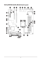
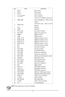
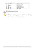
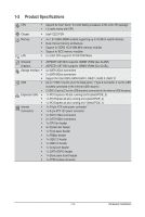
Item Code 1 PCIE_1 2 PCIE_2 3 PCIE_3 4 HD_AUDIO(Note) 5 USB2_LAN1 6 USB2_LAN2 7 VGA_1 8 COM1 9 P12V_AUX1 10 SYS_FAN1 11 PMBUS 12 IPMB 13 DDR3_P0_B1 14 DDR3_P0_B0 15 DDR3_P0_A1 16 DDR3_P0_A0 17 ATX 18 CPU 19 CPU0_FAN 20 SATA_SGP1 21 SYS_FAN3 22 SYS_FAN2 23 BIOS_PWD 24 PCH_ME 25 BIOS_RCVR 26 CLR_CMOS 27 SYS_FAN4 28 BAT 29 SATA_4_5 30 SATA_2_3 31 SATA0/SATA1 32 SATA_DOM1 33 SATA_DOM0 34 USB2_A1 35 F_USB3 36 ME_UPDATE 37 F_USB2 38 FP_1 Description PCI-E x4 slot PCI-E x8 slot PCI-E x16 slot Audio connectors LAN1 port (top/NCSI LAN port for server management) / USB 2.0 ports (bottom) LAN2 port (top) / USB 2.0 ports (bottom) VGA port Serial port 8 pin power connector System fan connector #1 PMBus connector IPMB connector DIMM slot (channel 2 slot 1 ) DIMM slot (channel 2 slot 0 ) DIMM slot (channel 1 slot 1 ) DIMM slot (channel 1 slot 0 ) 24 pin main power connector Intel LGA1150 socket CPU fan connector SATA SGPIO header System fan connector #3 System fan connector #2 Clearing supervisor password jumper ME recovery jumper BIOS Recovery jumper Clear CMOS jumper System fan connector # Battery socket SATA 3Gb/s connectors SATA 3Gb/s connectors SATA 6Gb/s connectors SATA port 1 DOM support jumper SATA port 0 DOM support jumper USB 2.0 Type A connector USB 3.0 header ME update jumper USB 2.0 Type A connector Front panel header NOTE! This feature/device is only for GA-6LASH. - 7 -
-
 1
1 -
 2
2 -
 3
3 -
 4
4 -
 5
5 -
 6
6 -
 7
7 -
 8
8 -
 9
9 -
 10
10 -
 11
11 -
 12
12 -
13
-
14
-
15
-
16
-
17
-
18
-
19
-
20
-
21
-
22
-
23
-
24
-
25
-
26
-
27
-
28
-
29
-
30
-
31
-
32
-
33
-
34
-
35
-
36
-
37
-
38
-
39
-
40
-
41
-
42
-
43
-
44
-
45
-
46
-
47
-
48
-
49
-
50
-
51
-
52
-
53
-
54
-
55
-
56
-
57
-
58
-
59
-
60
-
61
-
62
-
63
-
64
-
65
-
66
-
67
-
68
-
69
-
70
-
71
-
72
-
73
-
74
-
75
-
76
-
77
-
78
-
79
-
80
-
81
-
82
-
83
-
84
-
85
-
86
-
87
-
88
-
89
-
90
-
91
-
92
-
93
-
94
-
95
-
96
-
97
-
98
-
99
-
100
 |
 |