Gigabyte GA-6PXSV4 Manual - Page 7
Intel BD82C604 X79 chipset
 |
View all Gigabyte GA-6PXSV4 manuals
Add to My Manuals
Save this manual to your list of manuals |
Page 7 highlights
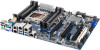
Item Code 1 LAN3_ACT 2 LAN4_ACT 3 ID_SW 4 MLAN 5 USB3_LAN1 6 USB3_LAN2 7 LAN3_4 8 VGA_COM1 9 PS2_USB2 10 P1 11 PWR_DET1 12 CPU_FAN1 13 CPU0 14 DDR3_P0_A0 15 DDR3_P0_A1 16 DDR3_P0_B0 17 DDR3_P0_B1 18 DDR3_P0_C0 19 DDR3_P0_C1 20 DDR3_P0_D0 21 DDR3_P0_D1 22 P1_CPU 23 SYS_FAN1/3 24 SYS_FAN2 25 SATA0/1 26 SATA2/3/4/5 27 F_PANEL_1 28 SATA_SGPIO 29 SATA_DOM1 30 U83 31 SATA_DOM0 32 BAT1 33 PASSWORD1 34 CASE_OPEN1 35 CLR_CMOS1 36 PBG_HS1 Description LAN3 active LED LAN4 active LED ID button 10/100 Management LANport RJ45 LAN port (top)/USB 3.0 ports (buttom) RJ45 LAN port (top)/USB 3.0 ports (buttom) RJ45 LAN port COM port (top)/VGA port (buttom) USB 2.0 ports (top)/PS/2 connector (buttom) 24 pin power connector PMBus connector CPU fan connector Intel LGA 2011 socket DIMM slot (channel 1 slot 0 ) DIMM slot (channel 1 slot 1 ) DIMM slot (channel 2 slot 0 ) DIMM slot (channel 2 slot 1 ) DIMM slot (channel 3 slot 0 ) DIMM slot (channel 3 slot 1 ) DIMM slot (channel 4 slot 0 ) DIMM slot (channel 4 slot 1 ) 8 pin power connector System fan #1/#3 connectors System fan #2 connector SATA 6Gb/s connectors SATA 3Gb/s connectors Front panel header SATA SGPIO header SATA port 1 DOM support jumper BIOS Upgrade ROM SATA port 0 DOM support jumper Battery socket Clear password jumper Chassis intrusion jumper Clear CMOS jumper Intel BD82C604 (X79) chipset - 7 -
-
 1
1 -
 2
2 -
 3
3 -
 4
4 -
 5
5 -
 6
6 -
 7
7 -
 8
8 -
 9
9 -
 10
10 -
 11
11 -
 12
12 -
13
-
14
-
15
-
16
-
17
-
18
-
19
-
20
-
21
-
22
-
23
-
24
-
25
-
26
-
27
-
28
-
29
-
30
-
31
-
32
-
33
-
34
-
35
-
36
-
37
-
38
-
39
-
40
-
41
-
42
-
43
-
44
-
45
-
46
-
47
-
48
-
49
-
50
-
51
-
52
-
53
-
54
-
55
-
56
-
57
-
58
-
59
-
60
-
61
-
62
-
63
-
64
-
65
-
66
-
67
-
68
-
69
-
70
-
71
-
72
 |
 |
