Gigabyte GA-6PXSV4 Manual - Page 8
iTE IT8728F Super I/O
 |
View all Gigabyte GA-6PXSV4 manuals
Add to My Manuals
Save this manual to your list of manuals |
Page 8 highlights
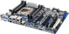
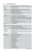
37 USB_A 38 BP_1 39 SAS0/1/2/3 40 BIOS_RCVR 41 F_USB3_1 42 F_USB_1 43 SAS_SGPIO 44 BIOS_WP 45 BMC_FRB1 46 TPM 47 COM2 48 PCI_1 49 PCIE1 50 PCIE2 51 PCIE3 52 PCIE4 53 U393 54 U392 55 BMC_LED1 56 SSB_ME1 57 U17 58 SYS_FAN4 59 U430 60 U15 61 U432 62 U442 63 U444 USB Type A connector Back plane board header SAS 3Gb/s connectors BIOS Recovery jumper USB 3.0 header USB 2.0 header SAS SGPIO header BIOS Write Protect jumper Force to Stop FRB3 Timer jumper TPM module connector Serial port cable header PCI 32bit/33MHz slot PCI-E x16 slot (Shared badwidth with PCIE3 slot) PCI-E x1 slot PCI-E x16 slot (Shared badwidth with PCIE1 slot) PCI-E slot BMC Upgrade ROM ASPEED AST2300 chipset BMC readiness LED ME Recovery jumper iTE IT8728F Super I/O System fan #4 connector Intel 82574L chipset EtronTech EJ188H chipset Intel 82574L chipset Intel 82574L chipset Intel 82574L chipset CAUTION! If a SATA type hard drive is connected to the motherboard, please ensure the jumper is closed and set to 2-3 pins (Normal mode), in order to reduce any risk of hard disk damage. Please refer to Page 32 for SATA_DOM0 and SATA_DOM1 jumper setting instruction. - 8 -
-
 1
1 -
2
-
 3
3 -
 4
4 -
 5
5 -
 6
6 -
 7
7 -
 8
8 -
 9
9 -
 10
10 -
 11
11 -
 12
12 -
 13
13 -
14
-
15
-
16
-
17
-
18
-
19
-
20
-
21
-
22
-
23
-
24
-
25
-
26
-
27
-
28
-
29
-
30
-
31
-
32
-
33
-
34
-
35
-
36
-
37
-
38
-
39
-
40
-
41
-
42
-
43
-
44
-
45
-
46
-
47
-
48
-
49
-
50
-
51
-
52
-
53
-
54
-
55
-
56
-
57
-
58
-
59
-
60
-
61
-
62
-
63
-
64
-
65
-
66
-
67
-
68
-
69
-
70
-
71
-
72
 |
 |
