Gigabyte GA-990FXA-UD5 Manual
Gigabyte GA-990FXA-UD5 Manual
 |
View all Gigabyte GA-990FXA-UD5 manuals
Add to My Manuals
Save this manual to your list of manuals |
Gigabyte GA-990FXA-UD5 manual content summary:
- Gigabyte GA-990FXA-UD5 | Manual - Page 1
GA-990FXA-UD5 User's Manual Rev. 1001 12ME-990FXA5-1001R - Gigabyte GA-990FXA-UD5 | Manual - Page 2
Motherboard GA-990FXA-UD5 May 20, 2011 Motherboard GA-990FXA-UD5 May 20, 2011 - Gigabyte GA-990FXA-UD5 | Manual - Page 3
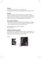
at: http://www.gigabyte.com Identifying Your Motherboard Revision The revision number on your motherboard looks like this: "REV: X.X." For example, "REV: 1.0" means the revision of the motherboard is 1.0. Check your motherboard revision before updating motherboard BIOS, drivers, or when looking - Gigabyte GA-990FXA-UD5 | Manual - Page 4
-UD5 Motherboard Layout 7 GA-990FXA-UD5 Motherboard Block Diagram 8 Chapter 1 Hardware Installation 9 1-1 Installation Precautions 9 1-2 Product Specifications 10 1-3 Installing the CPU and CPU Cooler 13 1-3-1 Installing the CPU 13 1-3-2 Installing the CPU Cooler 15 1-4 Installing the Memory - Gigabyte GA-990FXA-UD5 | Manual - Page 5
57 3-1 Installing Chipset Drivers 57 3-2 Application Software 58 3-3 Technical Manuals 58 3-4 Contact...59 3-5 System...59 3-6 Download Center 60 3-7 New Utilities...60 Chapter 4 Unique Features 61 4-1 Xpress Recovery2 61 4-2 BIOS Update Utilities 64 4-2-1 Updating the BIOS with the Q-Flash - Gigabyte GA-990FXA-UD5 | Manual - Page 6
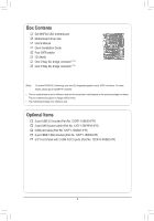
Contents GA-990FXA-UD5 motherboard Motherboard driver disk User's Manual Quick Installation Guide Four SATA cables I/O Shield One 2-Way SLI bridge connector (Note) One 3-Way SLI bridge connector (Note) (Note) To enable NVIDIA SLI technology, you need SLI-supported graphics cards, BIOS, and driver - Gigabyte GA-990FXA-UD5 | Manual - Page 7
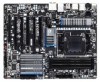
GA-990FXA-UD5 Motherboard Layout KB_MS_USB OPTICAL ATX_12V USB_1394_ESATA USB_ESATA Marvell 88SE9172 CPU_FAN Socket AM3+ PWR_FAN R_USB30 USB_LAN AUDIO Etron EJ168 Realtek RTL8111E PCIEX1(Note) PCIEX16_1 PCIEX4_1 AMD 990FX GA-990FXA-UD5 CODEC PCIEX16_2 PCIEX4_2 VIA VT6308 PCIEX8 PCI - Gigabyte GA-990FXA-UD5 | Manual - Page 8
GA-990FXA-UD5 Motherboard Block Diagram 2 PCI Express x8 1 PCI Express x16 1 PCI Express x16 CPU CLK+/- (200 MHz) or DDR3 2000(O.C.)/1866/1600/1333/1066 MHz AM3+/AM3 CPU Dual Channel Memory PCIe CLK (100 MHz) x8 x16 Switch x16 PCI Express Bus x4 x4 PCIe CLK (100 MHz) 2 PCI Express x4 PCI - Gigabyte GA-990FXA-UD5 | Manual - Page 9
or memory. If you do not have an ESD wrist strap, keep your hands dry and first touch a metal object to eliminate static electricity. • Prior to installing the motherboard, please have it on top of an antistatic pad or within an electrostatic shielding container. • Before unplugging the power supply - Gigabyte GA-990FXA-UD5 | Manual - Page 10
ŠŠ AM3+ Socket: - AMD AM3+ FX processors - AMD AM3 Phenom™ II processors/AMD Athlon™ II processors (Go to GIGABYTE's website for the latest CPU support list.) Hyper Transport Bus ŠŠ 5200 MT/s Chipset ŠŠ North Bridge: AMD 990FX ŠŠ South Bridge: AMD SB950 Memory ŠŠ 4 x 1.5V DDR3 DIMM sockets - Gigabyte GA-990FXA-UD5 | Manual - Page 11
header) 1 x 24-pin ATX main power connector 1 x 8-pin ATX 12V power connector 8 x SATA 6Gb/s connectors 1 x CPU fan header 2 x system fan headers 1 x power fan header 1 x front panel header 1 x front panel audio header 1 x S/PDIF Out header 3 x USB 2.0/1.1 headers 1 x USB 3.0/2.0 header 1 x IEEE - Gigabyte GA-990FXA-UD5 | Manual - Page 12
Features ŠŠ Support for @BIOS ŠŠ Support for Q-Flash ŠŠ Support for Xpress BIOS Rescue ŠŠ Support for Download Center ŠŠ Support for Xpress Install ŠŠ Support for Xpress Recovery2 ŠŠ Support for EasyTune * Available functions in EasyTune may differ by motherboard model. ŠŠ Support for - Gigabyte GA-990FXA-UD5 | Manual - Page 13
before you begin to install the CPU: • Make sure that the motherboard supports the CPU. (Go to GIGABYTE's website for the latest CPU support list.) • Always turn off the computer and unplug the power cord from the power outlet before installing the CPU to prevent hardware damage. • Locate the - Gigabyte GA-990FXA-UD5 | Manual - Page 14
below to correctly install the CPU into the motherboard CPU socket. • Before installing the CPU, make sure to turn off the computer and unplug the power cord from the power outlet to prevent damage to the CPU. • Do not force the CPU into the CPU socket. The CPU cannot fit in if oriented incorrectly - Gigabyte GA-990FXA-UD5 | Manual - Page 15
lock into place. (Refer to your CPU cooler installation manual for instructions on installing the cooler.) Step 5: Finally, attach the power connector of the CPU cooler to the CPU fan header (CPU_FAN) on the motherboard. Use extreme care when removing the CPU cooler because the thermal grease/tape - Gigabyte GA-990FXA-UD5 | Manual - Page 16
. If you are unable to insert the memory, switch the direction. 1-4-1 Dual Channel Memory Configuration This motherboard provides four DDR3 memory sockets and supports Dual Channel Technology. After the memory is installed, the BIOS will automatically detect the specifications and capacity of - Gigabyte GA-990FXA-UD5 | Manual - Page 17
to turn off the computer and unplug the power cord from the power outlet to prevent damage to the memory module. DDR3 and DDR2 DIMMs are not compatible to each other or DDR DIMMs. Be sure to install DDR3 DIMMs on this motherboard. Notch DDR3 DIMM A DDR3 memory module has a notch, so it can only fit - Gigabyte GA-990FXA-UD5 | Manual - Page 18
motherboard supports the expansion card. Carefully read the manual that came with your expansion card. • Always turn off the computer and unplug the power cord from the power , go to BIOS Setup to make any required BIOS changes for your expansion card(s). 7. Install the driver provided with the - Gigabyte GA-990FXA-UD5 | Manual - Page 19
driver ( Current GPUs that support 3-Way CrossFireX technology include the ATI Radeon HD 3800, HD 4800, and HD 5800 series and AMD Radeon HD 6950, HD 6970 and HD 6990 series.) - CrossFireX bridge connector(s) (Note) - A power supply with sufficient power is recommended (refer to the manual - Gigabyte GA-990FXA-UD5 | Manual - Page 20
Drive(s)," for instructions on configuring a RAID array. USB 3.0/2.0 Port The USB 3.0 port supports the USB 3.0 specification and is compatible to the USB 2.0/1.1 specification. Use this port for USB devices such as a USB keyboard/mouse, USB printer, USB flash drive and etc. RJ-45 LAN Port The - Gigabyte GA-990FXA-UD5 | Manual - Page 21
to the default Mic in jack ( ). Refer to the instructions on setting up a 2/4/5.1/7.1-channel audio configuration in Chapter 5, "Configuring , first remove the cable from your device and then remove it from the motherboard. •• When removing the cable, pull it straight out from the connector. - Gigabyte GA-990FXA-UD5 | Manual - Page 22
8 7 4 11 10 17 14 4 15 12 13 16 9 1) ATX_12V 2) ATX 3) CPU_FAN 4) SYS_FAN1/2 5) PWR_FAN 6) BAT 7) SATA3_0/1/2/3/4/5 8) GSATA3_6/7 9) F_PANEL 10) to turn off the devices and your computer. Unplug the power cord from the power outlet to prevent damage to the devices. • After installing the - Gigabyte GA-990FXA-UD5 | Manual - Page 23
1/2) ATX_12V/ATX (2x4 12V Power Connector and 2x12 Main Power Connector) With the use of the power connector, the power supply can supply enough stable power to all the components on the motherboard. Before connecting the power connector, first make sure the power supply is turned off and all - Gigabyte GA-990FXA-UD5 | Manual - Page 24
wire is the ground wire). The motherboard supports CPU fan speed control, which requires the use of a CPU fan with fan speed control design. terminals of the battery holder, making them short for 5 seconds.) 333 Replace the battery. 444 Plug in the power cord and restart your computer. •• Always - Gigabyte GA-990FXA-UD5 | Manual - Page 25
/s standard and are compatible with SATA 3Gb/s and SATA 1.5Gb/s standards. Each SATA connector supports a single SATA device. The AMD SB950 South Bridge supports RAID 0, RAID 1, RAID 5, RAID 10, and JBOD. Refer to Chapter 5, "Configuring SATA Hard Drive(s)," for instructions on configuring a RAID - Gigabyte GA-990FXA-UD5 | Manual - Page 26
beep code. One single short beep will be heard if no problem is detected at system startup. If a problem is detected, the BIOS may issue beeps in different patterns to indicate the problem. Refer to Chapter 5, "Troubleshooting," for information about beep of power switch, reset switch, power LED, - Gigabyte GA-990FXA-UD5 | Manual - Page 27
panel audio module, refer to the instructions on how to activate AC'97 supports digital S/PDIF Out and connects a S/PDIF digital audio cable (provided by expansPioCnIe cpoawrdersc)ofnonrecdtoigr (iStaAlTAa)u(Xd5i8oAo-OuCtp) ut from your motherboard the manual for your expansion card. Pin No. Definition - Gigabyte GA-990FXA-UD5 | Manual - Page 28
the local dealer. Pin No. Definition 1 Power (5V) 9 1 2 Power (5V) 10 2 3 USB DX- 4 USB DY- 5 USB DX+ 6 USB DY+ 7 GND 8 GND 9 No Pin 10 NC 13) F_USB30 (USB 3.0/2.0 Header) The header conforms to USB 3.0/2.0 specification and can provide two USB ports. For purchasing the optional - Gigabyte GA-990FXA-UD5 | Manual - Page 29
bracket, please con- tact the local dealer. Pin No. Definition 1 TPA+ 9 1 2 TPA- 10 2 3 GND- 4 GND 5 TPB+ 6 TPB- 7 Power (12V) 8 Power (12V) 9 No Pin 10 GND • Do not plug the USB bracket cable into the IEEE 1394a header. • Prior to installing the IEEE 1394a bracket, be sure to turn - Gigabyte GA-990FXA-UD5 | Manual - Page 30
Short: Clear CMOS Values •• Always turn off your computer and unplug the power cord from the power motherboard. •• After system restart, go to BIOS Setup to load factory defaults (select Load Optimized Defaults) or manually configure the BIOS settings (refer to Chapter 2, "BIOS Setup," for BIOS - Gigabyte GA-990FXA-UD5 | Manual - Page 31
do not encounter problems using the current version of BIOS, it is recommended that you not flash the BIOS. To flash the BIOS, do it with caution. Inadequate BIOS flashing may result in system malfunction. • BIOS will emit a beep code during the POST. Refer to Chapter 5, "Troubleshooting," for the - Gigabyte GA-990FXA-UD5 | Manual - Page 32
A. The LOGO Screen (Default) Function Keys B. The POST Screen Motherboard Model BIOS Version Award Modular BIOS v6.00PG Copyright (C) 1984-2011, Award Software, Inc. GA-990FXA-UD5 F1a . . . . : BIOS Setup : XpressRecovery2 : Boot Menu : Qflash 04/26/2011-RD990-SB950-7A66FG04C - Gigabyte GA-990FXA-UD5 | Manual - Page 33
Standard CMOS Features Advanced BIOS Features Integrated Peripherals Power Management Setup PC Health Status Load Item F10: Save & Exit Setup Change CPU's Clock & Voltage F11: Save CMOS to BIOS F12: Load CMOS from BIOS BIOS Setup Program Function Keys Move the selection - Gigabyte GA-990FXA-UD5 | Manual - Page 34
BIOS Features Use this menu to configure the device boot order, advanced features available on the CPU, and the primary display adapter. Integrated Peripherals Use this menu to configure all peripheral devices, such as SATA, USB, integrated audio, and integrated LAN, etc. Power Management - Gigabyte GA-990FXA-UD5 | Manual - Page 35
to boot. If this occurs, clear the CMOS values and reset the board to CPU Clock Ratio Allows you to alter the clock ratio for the installed CPU. The adjustable range is dependent on the CPU being used. (Note) This item is present only when you install a CPU that supports this feature. - 35 - BIOS - Gigabyte GA-990FXA-UD5 | Manual - Page 36
allows the BIOS to automatically adjust the CPU host frequency. Manual allows the CPU Frequency (MHz) item below to be configurable. Note: If your system fails to boot after overclocking, please wait for 20 seconds to allow for automated system reboot, or clear the CMOS values to reset the board to - Gigabyte GA-990FXA-UD5 | Manual - Page 37
CPU Host Clock Control x CPU Frequency(MHz) Set Memory Clock x Memory Channel Interleaving Bank Interleaving DQS Training Control CKE Power Down Mode Memclock tri-stating [Enabled] [ Optimized Defaults CPU Host Clock Control, CPU Frequency (MHz), Set Memory Clock, Memory Clock The - Gigabyte GA-990FXA-UD5 | Manual - Page 38
, 1.5x, 2.0x. CS/ODT Drive Strength Options are: Auto (default), 1.0x, 1.25x, 1.5x, 2.0x. CKE Drive Strength Options are: Auto (default), 1.0x, 1.25x, 1.5x, 2.0x. BIOS Setup - 38 - - Gigabyte GA-990FXA-UD5 | Manual - Page 39
set the system voltages. Auto lets the BIOS automatically set the system voltages as required. Manual allows all voltage control items below to be configurable. (Default: Auto) CPU PLL Voltage Control Allows you to set the CPU PLL voltage. Normal Supplies the CPU PLL voltage as required. (Default - Gigabyte GA-990FXA-UD5 | Manual - Page 40
range is from 1.025V to 2.135V. Note: Increasing memory voltage may result in damage to the memory or reduce the useful life of the memory. DDR VTT Voltage Control Allows you to set the memory VTT voltage. Normal Supplies the memory VTT voltage as required. (Default) 0.515V ~ 1.145V The - Gigabyte GA-990FXA-UD5 | Manual - Page 41
[None] [None] [None] Halt On [All, But Keyboard] Base Memory Extended Memory 640K 1022M Move Enter: Select F5: Previous Values +/-/PU/PD: Value the two methods below: • Auto Lets the BIOS automatically detect SATA devices during the POST. (Default) • None If no SATA - Gigabyte GA-990FXA-UD5 | Manual - Page 42
stop for any error. All, But Keyboard The system boot will not stop for a keyboard error but stop for all other errors. (Default) Memory These fields are read-only and are determined by the BIOS POST. Base Memory Also called conventional memory. Typically, 640 KB will be reserved for the - Gigabyte GA-990FXA-UD5 | Manual - Page 43
BIOS Features AMD C1E Support (Note) Virtualization AMD K8 Cool&Quiet control CPU Unlock (Note) CPU core Control (Note) x CPU core 0 (Note) x CPU core 1 (Note) x CPU core 2/3/4/5 (Note) } Hard Disk Boot Priority EFI CD/DVD Boot Option First Boot Device Second Boot - Gigabyte GA-990FXA-UD5 | Manual - Page 44
) Full Screen LOGO Show Allows you to determine whether to display the GIGABYTE Logo at system startup. Disabled displays normal POST message. (Default: Enabled) IOMMU support Enables or disables AMD IOMMU support. (Default: Disabled) Init Display First Specifies the first initiation of the monitor - Gigabyte GA-990FXA-UD5 | Manual - Page 45
eSATA3 Ctrl Mode GSATA3 Controller GSATA3 Ctrl Mode Onboard LAN Function Onboard LAN Boot ROM } SMART LAN Onboard Audio Function Onboard 1394 Function R_USB3.0 Controller USB Controllers USB Legacy Function [Enabled] [Native IDE] IDE Enabled [Enabled] Press - Gigabyte GA-990FXA-UD5 | Manual - Page 46
SATA Type The mode depends on the OnChip SATA Type settings. OnChip SATA RAID5 Support (AMD SB950 South Bridge, SATA3_0~SATA3_5 connectors) Enables or disables RAID 5 support for the SATA controller integrated in the AMD SB950 South Bridge. This option is configurable only when OnChip SATA Type is - Gigabyte GA-990FXA-UD5 | Manual - Page 47
(AHCI) is an interface specification that allows the storage driver to enable advanced Serial ATA features such as Native Command or short. Refer to the following information for diagnosing your LAN cable: When No LAN Cable Is Attached... If no LAN cable is attached to the motherboard, the - Gigabyte GA-990FXA-UD5 | Manual - Page 48
it will operate at a normal speed of 10/100/1000 Mbps in Windows mode or when the LAN Boot ROM is activated. When a Cable Problem Occurs... If a cable problem occurs on a specified pair of wires, the Status field will show Short and then length shown will be the approximate distance to the fault or - Gigabyte GA-990FXA-UD5 | Manual - Page 49
Allows the system to be awakened from an ACPI sleep state by a wake-up signal from a PCI or PCIe device. Note: To use this function, you need an ATX power supply providing at least 1A on the +5VSB lead. (Default: Enabled) (Note) Supported on Windows 7/Vista operating system only. - 49 - BIOS Setup - Gigabyte GA-990FXA-UD5 | Manual - Page 50
Click Double click on left button on the PS/2 mouse to turn on the system. Power On By Keyboard Allows the system to be turned on by a PS/2 keyboard wake-up event. Note: you need an ATX power supply providing at least 1A on the +5VSB lead. Disabled Disables this function. (Default) Password Set - Gigabyte GA-990FXA-UD5 | Manual - Page 51
Control Reset Case Open Status Case Opened Vcore DDR3 1.5V +3.3V +12V Current System Temperature Current CPU Temperature Current CPU FAN Speed Current SYSTEM FAN1 Speed Current SYSTEM FAN2 Speed Current POWER FAN Speed CPU Warning Temperature CPU FAN - Gigabyte GA-990FXA-UD5 | Manual - Page 52
. Current System/CPU Temperature Displays current system/CPU temperature. Current CPU/SYSTEM/POWER FAN Speed (RPM) Displays current CPU/system/power fan speed. CPU Warning Temperature Sets the warning threshold for CPU temperature. When CPU temperature exceeds the threshold, BIOS will emit warning - Gigabyte GA-990FXA-UD5 | Manual - Page 53
Defaults Advanced BIOS Features Set Supervisor Password Integrated Peripherals Set User Password Power Management Setup Load Fail-Safe defaults, which are the safest and most stable BIOS settings for the motherboard. 2-10 Load Optimized Defaults CMOS Setup Utility-Copyright (C) - Gigabyte GA-990FXA-UD5 | Manual - Page 54
Standard CMOS Features Advanced BIOS Features Integrated Peripherals Power Management SetupEnter Password: PC Health boot. In BIOS Setup, you must enter the supervisor password if you wish to make changes to BIOS settings. The user password only allows you to view the BIOS settings - Gigabyte GA-990FXA-UD5 | Manual - Page 55
(M.I.T.) Load Fail-Safe Defaults Standard CMOS Features Advanced BIOS Features Load Optimized Defaults Save to CMOS and EXIT (Y/N)? Y Set Supervisor Password Integrated Peripherals Set User Password Power Management Setup Save & Exit Setup PC Health Status Exit - Gigabyte GA-990FXA-UD5 | Manual - Page 56
BIOS Setup - 56 - - Gigabyte GA-990FXA-UD5 | Manual - Page 57
install new GIGABYTE utilities. Click Yes to automatically install the utilities. Or click No if you want to manually select the utilities to install on the Application Software page later. • For USB 2.0 driver support under the Windows XP operating system, please install the Windows XP Service Pack - Gigabyte GA-990FXA-UD5 | Manual - Page 58
applications that GIGABYTE develops and some free software. You can click the Install button on the right of an item to install it. 3-3 Technical Manuals This page provides GIGABYTE's application guides, content descriptions for this driver disk, and the motherboard manuals. Drivers Installation - Gigabyte GA-990FXA-UD5 | Manual - Page 59
3-4 Contact For the detailed contact information of the GIGABYTE Taiwan headquarter or worldwide branch offices, click the URL on this page to link to the GIGABYTE website. 3-5 System This page provides the basic system information. - 59 - Drivers Installation - Gigabyte GA-990FXA-UD5 | Manual - Page 60
3-6 Download Center To update the BIOS, drivers, or applications, click the Download Center button to link to the GIGABYTE website. The latest version of the BIOS, drivers, or applications will be displayed. 3-7 New Utilities This page provides a quick link to GIGABYTE's lately developed utilities - Gigabyte GA-990FXA-UD5 | Manual - Page 61
system and drivers are installed. • of system memory • VESA compatible graphics card USB hard drives are not supported. • RAID drives are not supported. • GPT partitions are not supported. • Hard drives larger than 2.2 TB are not supported. Installation and Configuration: Turn on your system to boot - Gigabyte GA-990FXA-UD5 | Manual - Page 62
save the backup file. B. Accessing Xpress Recovery2 1. Boot from the motherboard driver disk to access Xpress Recovery2 for the first time. to enter Xpress Recovery2 later, simply press during the POST. C. Using the Backup Function in Xpress Recovery2 Xpress Recovery2 will automatically - Gigabyte GA-990FXA-UD5 | Manual - Page 63
D. Using the Restore Function in Xpress Recovery2 Select RESTORE to restore the backup to your hard drive in case the system breaks down. The RESTORE option will not be present if no backup is created before. E. Removing the Backup Step 1: If you wish to remove the backup file, select REMOVE. Step - Gigabyte GA-990FXA-UD5 | Manual - Page 64
if the BIOS update file is saved to a hard drive in RAID/AHCI mode or a hard drive attached to an independent SATA controller, use the key during the POST to access Q-Flash. Award Modular BIOS v6.00PG Copyright (C) 1984-2011, Award Software, Inc. GA-990FXA-UD5 F1a . . . . : BIOS Setup - Gigabyte GA-990FXA-UD5 | Manual - Page 65
Enter : Run hi:Move Total size : 0 ESC:Reset Free size : 0 F10:Power Off 3. Select the BIOS update file and press . Make sure the BIOS update file matches your motherboard model. Step 2: The process of the system reading the BIOS file from the USB flash drive is displayed on the screen - Gigabyte GA-990FXA-UD5 | Manual - Page 66
. As the system boots, you should see the new BIOS version is present on the POST screen. Step 5: During the POST, press to enter BIOS Setup. Select Load Optimized Defaults and press to load BIOS defaults. System will re-detect all peripheral devices after a BIOS update, so we - Gigabyte GA-990FXA-UD5 | Manual - Page 67
. If the BIOS update file for your motherboard is not present on the @BIOS server site, please manually download the BIOS update file from GIGABYTE's website and follow the instructions in "Update the BIOS without Using the Internet Update Function" below. 2. Update the BIOS without Using the - Gigabyte GA-990FXA-UD5 | Manual - Page 68
in EasyTune 6 may differ by motherboard model. Grayed-out area(s) indicates that the item is not configurable or the function is not supported. Incorrectly doing overclock/overvoltage may result in damage to the hardware components such as CPU, chipset, and memory and reduce the useful life of - Gigabyte GA-990FXA-UD5 | Manual - Page 69
Saver Interface A. Meter Mode In Meter Mode, GIGABYTE Easy Energy Saver shows how much power they have saved in a set period of Update (Check for the latest utility version) • The above data is for reference only. Actual performance may vary depending on motherboard model. • CPU Power and Power - Gigabyte GA-990FXA-UD5 | Manual - Page 70
(Application will continue to run in taskbar) 13 INFO/Help 14 Live Utility Update (Check for the latest utility version) C. Stealth Mode In Stealth Mode, the system continues to work with the user-defined power saving settings, even after the system is restarted. Re-enter the application only - Gigabyte GA-990FXA-UD5 | Manual - Page 71
LAN connection settings and Q-Share, you are able to share your data with computers on the same network, making full use of Internet resources. Directions for using Q-Share After installing Q-Share from the motherboard driver disk, go to Start>All Programs>GIGABYTE (Note) Updates Q-Share online - Gigabyte GA-990FXA-UD5 | Manual - Page 72
is reached, the oldest backup will be ovewritten. Instructions for copying files/folders from a backup: To to copy and click the Copy button. The files/folders listed on the screen are read-only so you cannot edit the backup will be performed on the next boot. We recommend that you preserve at least - Gigabyte GA-990FXA-UD5 | Manual - Page 73
Enters Suspend to RAM mode Disables this function The Bluetooth dongle included in the motherboard package(Note 2) allows you to wake up the system from Suspend to RAM mode without the need to press the power button first. (Note 1) (Note 2) If your cell phone has been configured as the Auto - Gigabyte GA-990FXA-UD5 | Manual - Page 74
, CPU VCore and system temperature. • Control (System Status Control): The Control tab allows for controlling system power states with restart, power off, suspend, and hibernate options. (Note 1) (Note 2) (Note 3) Supported on Windows 7, Vista, and XP. For Windows XP, be sure to update Internet - Gigabyte GA-990FXA-UD5 | Manual - Page 75
BIOS Setup. C. Configure a RAID array in RAID BIOS. (Note 1) D. Install the SATA RAID/AHCI driver disk. • Motherboard driver disk. • A USB floppy disk drive motherboard, the SATA3_0~SATA3_5 ports are supported by the AMD SB950 South Bridge.) Then connect the power connector from your power supply - Gigabyte GA-990FXA-UD5 | Manual - Page 76
mode correctly in system BIOS Setup. Step 1: Turn on your computer and press to enter BIOS Setup during the POST (Power-On Self-Test). Make LAN Function Onboard LAN Boot ROM } SMART LAN Onboard Audio Function Onboard 1394 Function R_USB3.0 Controller USB Controllers USB - Gigabyte GA-990FXA-UD5 | Manual - Page 77
for a non-RAID configuration. Step 1: After the POST memory test begins and before the operating system boot begins, look for a message which says "Press to enter RAID Option ROM Utility" (Figure 2). Press + to enter the RAID BIOS setup utility. RAID Option ROM Version 3.3.1540 - Gigabyte GA-990FXA-UD5 | Manual - Page 78
Create Arrays Manually To create a new array, press to enter the LD View Menu Name LD 1 Logical Drive 1 [ LD Define Menu ] RAID Mode Drv RAID 0 0 Stripe Block Gigabyte Boundary Read Policy 64 KB ON Read Ahead Initialization ON Write Policy WriteBack [ Drives Assignments ] Port:ID - Gigabyte GA-990FXA-UD5 | Manual - Page 79
where you will see the newlycreated array. 9. Press to return to Main Menu and press again if you want to exit the RAID BIOS utility. - 79 - Appendix - Gigabyte GA-990FXA-UD5 | Manual - Page 80
View Drive Assignments The View Drive Assignments option in the Main Menu displays whether the attached hard drives are assigned to a disk array or are unassigned. Under the Assignment column, drives are labeled with their assigned disk array or shown as Free if unassigned. Option ROM Utility (c) - Gigabyte GA-990FXA-UD5 | Manual - Page 81
on the motherboard. One of the Marvell 88SE9172 SATA controllers controls the onboard GSATA3_6/7 connector and the other controls the eSATA ports on the back panel. Then connect the power connector from your power supply to the hard drive. B. Configuring SATA controller and RAID mode in BIOS Setup - Gigabyte GA-990FXA-UD5 | Manual - Page 82
to the installation of Windows operating system for a non-RAID configuration. After the POST memory test begins and before the operating system boot begins, look for a message which says "Press + to enter BIOS Setup or to continue" (Figure 2). Press + to enter the RAID - Gigabyte GA-990FXA-UD5 | Manual - Page 83
screen, press on the RAID tab. Then the RAID Config menu appears (Figure 4). Press on the Create VD item. Marvell BIOS Setup (c) 2009 Marvell Technology Group Ltd. [ Selection] [ Adapter] [ Devices] [ RAID ] RAID Config Create VD Delete VD Wipe out disk Spare Management ENTER - Gigabyte GA-990FXA-UD5 | Manual - Page 84
write-back or write-through cache. 5. VD Name: Enter an array name with 1~10 letters (letters cannot be special characters). Marvell BIOS Setup (c) 2009 Marvell Technology Group Ltd. [ Selection] [ Adapter] [ Devices] [ RAID ] Select free disks to create PCorrteate VD Disk Name * S0 * S1 - Gigabyte GA-990FXA-UD5 | Manual - Page 85
the message "Do you want to delete the VD's MBR?" appears, press to clear the MBR or press other keys to ignore. Marvell BIOS Setup (C) 2009 Marvell Technology Group Ltd. [ Selection] [ Adapter] [ Devices] [ RAID ] RAID Config Delete VD ID * 0 Name GBT Size 152.4GB Level RAID0 Status - Gigabyte GA-990FXA-UD5 | Manual - Page 86
utility, you can set up an array or view the current array status in the operating system. To install the utility, insert the motherboard driver disk, then go to Application Software\Install Application Software and select Marvell Storage Utility to install. Note: After the installation, you must - Gigabyte GA-990FXA-UD5 | Manual - Page 87
instructions use Windows 7 as the example operating system.) Step 1: Boot from the Windows 7/Vista setup disk and perform standard OS installation steps. When you arrive at the "Where do you want to install Windows?" screen, select Load Driver. Step 2: For the AMD SB950: Insert the motherboard - Gigabyte GA-990FXA-UD5 | Manual - Page 88
88SE9172: Step 2: Insert the motherboard driver disk and then browse to the location of the driver. The locations of the drivers are as follows: RAID driver for Windows 32-bit: \BootDrv\Marvell\RAID\i386 RAID driver for Windows 64-bit: \BootDrv\Marvell\RAID\amd64 AHCI driver for Windows 32-bit - Gigabyte GA-990FXA-UD5 | Manual - Page 89
First, copy the driver from the motherboard driver disk to a floppy disk. Refer to the methods below. Method A: • For the AMD SB950, copy all files (if you're using a USB floppy disk drive, make sure it is designated as drive A). Select the controller driver by pressing the corresponding letter from - Gigabyte GA-990FXA-UD5 | Manual - Page 90
with Windows, using a device support disk provided by an adapter manufacturer. Select the SCSI Adapter you want from the following list, or press ESC to return to the previous screen. AMD AHCI Compatible RAID Controller-x86 platform AMD AHCI Compatible RAID Controller-x64 platform ENTER - Gigabyte GA-990FXA-UD5 | Manual - Page 91
screen, press to continue the driver installation. Windows Setup You have chosen to configure a SCSI Adapter for use with Windows, using a device support disk provided by an adapter manufacturer. Select the SCSI Adapter you want from the following list, or press ESC to return to the - Gigabyte GA-990FXA-UD5 | Manual - Page 92
drive is added to replace a failed drive to rebuild a RAID 1 array. For the AMD SB950: While in the operating system, make sure the chipset drivers have been installed from the motherboard driver disk. Then launch the AMD RAIDXpert from All Programs in the Start Menu. Step 1: Enter the login ID and - Gigabyte GA-990FXA-UD5 | Manual - Page 93
set the new hard drive as a Spare drive in the RAID setup utility first. • Enabling Automatic Rebuild Step 1: When the message "Press + to enter BIOS Setup or to continue" appears, press + to enter the RAID setup utility. On the main screen, press on the RAID tab - Gigabyte GA-990FXA-UD5 | Manual - Page 94
you have installed the Marvell RAID driver and Marvell Storage Utility from the motherboard driver disk. While in the operating system completed, the status will display as Done. • Manually Rebuilding RAID 1 in the Operating System You can manually rebuild a RAID 1 array without setting the new - Gigabyte GA-990FXA-UD5 | Manual - Page 95
audio driver. For manually configure the jack for microphone functionality. • Audio signals will be present on both of the front and back panel audio connections simultaneously. If you want to mute the back panel audio (only supported when using an HD front panel audio module), refer to instructions - Gigabyte GA-990FXA-UD5 | Manual - Page 96
the type of device you connect. Then click OK. Step 3: On the Speakers screen, click the Speaker Configuration tab. In the Speaker Configuration list, select Stereo, Quadraphonic, 5.1 Speaker, or 7.1 Speaker according to the type of speaker configuration you wish to set up. Then the speaker setup is - Gigabyte GA-990FXA-UD5 | Manual - Page 97
5-2-2 Configuring S/PDIF Out The S/PDIF Out jack can transmit audio signals to an external decoder for decoding to get the best audio quality. 1. Connecting a S/PDIF Out Cable: Connect a S/PDIF optical cable to the corresponding S/PDIF out connector as shown below and an external decoder for - Gigabyte GA-990FXA-UD5 | Manual - Page 98
5-2-3 Enabling the Dolby Home Theater Function Before Dolby Home Theater is enabled, you get only 2-channel playback output (from the front speakers) when playing 2-channel stereo sources. You must play 4-, 5.1-, or 7.1- channel content to get 4-, 5.1-, or 7.1- channel audio effects. With Dolby Home - Gigabyte GA-990FXA-UD5 | Manual - Page 99
5-2-4 Configuring Microphone Recording Step 1: After installing the audio driver, the HD Audio Manager icon will appear in the notification area. Double-click the icon to access the HD Audio Manager. Step 2: Connect your microphone - Gigabyte GA-990FXA-UD5 | Manual - Page 100
Step 5: After completing the settings above, click Start, point to All Programs, point to Accessories, and then click Sound Recorder to begin the sound recording. * Enabling Stereo Mix If the HD Audio Manager does not display the recording device you wish to use, refer to the steps below. The - Gigabyte GA-990FXA-UD5 | Manual - Page 101
. Be sure to save the recorded audio file upon completion. B. Playing the Recorded Sound You can play your recording in a digital media player program that supports your audio file format. - 101 - Appendix - Gigabyte GA-990FXA-UD5 | Manual - Page 102
Support & Downloads\FAQ page on our website and search for "onboard HD audio driver." Q: What do the beeps emitted during the POST mean? A: The following Award BIOS beep code descriptions may help you identify possible computer problems. (For reference only.) 1 short: System boots successfully - Gigabyte GA-990FXA-UD5 | Manual - Page 103
the CPU cooler power cable to the motherboard. Yes The problem is verified and solved. Check if the memory is installed properly on the memory slot. No Correctly insert the memory into the memory socket. Yes The problem is verified and solved. Insert the graphics card. Connect the ATX - Gigabyte GA-990FXA-UD5 | Manual - Page 104
When the computer is turned on, is the CPU cooler running? No The power supply, CPU or CPU socket might fail. Yes Check if there is display on your monitor. Yes Turn off the computer. Plug in the keyboard and mouse and restart the computer. The problem is verified and solved. No The graphics - Gigabyte GA-990FXA-UD5 | Manual - Page 105
- 105 - Appendix - Gigabyte GA-990FXA-UD5 | Manual - Page 106
Appendix - 106 - - Gigabyte GA-990FXA-UD5 | Manual - Page 107
City 231,Taiwan TEL: +886-2-8912-4000 FAX: +886-2-8912-4003 Tech. and Non-Tech. Support (Sales/Marketing) : http://ggts.gigabyte.com.tw WEB address (English): http://www.gigabyte.com WEB address (Chinese): http://www.gigabyte.tw • G.B.T. INC. - U.S.A. TEL: +1-626-854-9338 FAX: +1-626-854-9339 Tech - Gigabyte GA-990FXA-UD5 | Manual - Page 108
.com.ro • Serbia WEB address : http://www.gigabyte.co.rs • Kazakhstan WEB address : http://www.gigabyte.kz You may go to the GIGABYTE website, select your language in the language list on the top right corner of the website. • GIGABYTE Global Service System To submit a technical or non-technical
-
 1
1 -
 2
2 -
 3
3 -
 4
4 -
 5
5 -
 6
6 -
 7
7 -
8
-
9
-
10
-
11
-
12
-
13
-
14
-
15
-
16
-
17
-
18
-
19
-
20
-
21
-
22
-
23
-
24
-
25
-
26
-
27
-
28
-
29
-
30
-
31
-
32
-
33
-
34
-
35
-
36
-
37
-
38
-
39
-
40
-
41
-
42
-
43
-
44
-
45
-
46
-
47
-
48
-
49
-
50
-
51
-
52
-
53
-
54
-
55
-
56
-
57
-
58
-
59
-
60
-
61
-
62
-
63
-
64
-
65
-
66
-
67
-
68
-
69
-
70
-
71
-
72
-
73
-
74
-
75
-
76
-
77
-
78
-
79
-
80
-
81
-
82
-
83
-
84
-
85
-
86
-
87
-
88
-
89
-
90
-
91
-
92
-
93
-
94
-
95
-
96
-
97
-
98
-
99
-
100
-
101
-
102
-
103
-
104
-
105
-
106
-
107
-
108
 |
 |

GA-990FXA-UD5
User's Manual
Rev. 1001
12ME-990FXA5-1001R