Gigabyte GA-9SISL Manual - Page 14
Back Panel Connectors
 |
View all Gigabyte GA-9SISL manuals
Add to My Manuals
Save this manual to your list of manuals |
Page 14 highlights
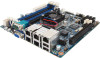
1-4 Back Panel Connectors Power Button and LED Press this button to hard reset and power on the system. Color Status Description Green On System is powered on. Green Blink System is in ACPI S1 state (sleep mode) N/A Off • • System is not powered on or in ACPI S5 state (power off) System is in ACPI S4 state (hibernate mode) ID Button and LED This button provides the selected unit idfication function. Color Status Description Blue On Unit selected for identification. N/A Off No identification. System Status LED Display the system health status. Color Status Description Green Amber N/A On Running or normal operation. On There is at least one sensor that has critical alter. Off System is not ready. Serial Port Connects to serial-based mouse or data processing devices. VGA Port The video in port allows connect to video in, which can also apply to video loop thru function. RJ-45 LAN Port The Gigabit Ethernet LAN port provides Internet connection at up to 1 Gbps data rate. The following describes the states of the LAN port LEDs. KVM Server Management 10/100 LAN Port (Dedicated LAN Port) The LAN port provides Internet connection with data transfer speeds of 10/100Mbps. This port is the decated LAN port for server management. USB 2.0 Port The USB port supports the USB 2.0 specification. Use this port for USB devices such as a USB keyboard/mouse, USB printer, USB flash drive and etc. Hardware Installation - 14 -
-
 1
1 -
2
-
3
-
4
-
5
-
6
-
7
-
8
-
 9
9 -
 10
10 -
 11
11 -
 12
12 -
 13
13 -
 14
14 -
 15
15 -
 16
16 -
 17
17 -
 18
18 -
 19
19 -
20
-
21
-
22
-
23
-
24
-
25
-
26
-
27
-
28
-
29
-
30
-
31
-
32
-
33
-
34
-
35
-
36
-
37
-
38
-
39
-
40
-
41
-
42
-
43
-
44
-
45
-
46
-
47
-
48
-
49
-
50
-
51
-
52
-
53
-
54
-
55
-
56
-
57
-
58
-
59
-
60
-
61
-
62
-
63
-
64
-
65
-
66
-
67
-
68
-
69
-
70
-
71
-
72
-
73
-
74
-
75
-
76
-
77
-
78
-
79
-
80
-
81
-
82
-
83
-
84
 |
 |
