Gigabyte GA-9SISL Manual - Page 7
BMC Management LAN port top / USB
 |
View all Gigabyte GA-9SISL manuals
Add to My Manuals
Save this manual to your list of manuals |
Page 7 highlights
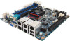
Item Code 1 USB_MLAN 2 LAN1_2 3 LAN3_4 4 VGA_COM1 5 LED_STA 6 SW_ID 7 SW_PWR 8 P12V_AUX1 9 ATX1 10 DIMM_P0_A0 11 DIMM_P0_A1 12 DIMM_P0_B0 13 DIMM_P0_B0 14 BAT1 15 SYS_FAN1 16 BP_1 17 PH_LED 18 BIOS_PWD 19 CLR_CMOS 20 BIOS_RCVR 21 PMBUS 22 SATA2/3/4/5 23 FP_2 24 SATA0/1 25 SATA_DOM0 26 ACK_SEL1 27 LED_BMC 28 CPU 29 U351 30 PCIE_1 31 IPMB 32 BMC_FLH1 33 TPM 34 CPU_FAN 35 S3_MASK Description BMC Management LAN port (top) / USB 2.0 ports (bottom) LAN1port (top) and LAN2 port (bottom) LAN3port (top) and LAN4 port (bottom) Serial port (top) / VGA port (bottom) System status LED ID Switch button Power button 8 pin power connector 24 pin main power connector DIMM slot/Channel 1 slot 0 DIMM slot/Channel 1 slot 1 DIMM slot/Channel 2 slot 0 DIMM slot/Channel 2 slot 1 Battery socket System fan connector HDD back plane board header Case open intrusion/LAN prot 3 & port 4 Active/HDD LED header Clearning supervisor password jumper Clear CMOS jumper BIOS recovery jumper PMBus connector SATA 3Gb/s connectors Front panel header SATA 6Gb/s connectors SATA port 0 DOM support jumper 4 Nodes System and Rack System switch jumper BMC readiness LED CPU ASPEED BMC chipset PCI-E x16 slot IPMB connector BMC Flash/Upgrade ROM TPM module connector CPU fan connector S3 Power On Select jumper CAUTION! If a SATA type hard drive is connected to the motherboard, please ensure the jumper is closed and set to 2-3 pins (Default setting), in order to reduce any risk of hard disk damage. Please refer to Page 25 for SATA_DOM0 jumper setting instruction. - 7 -
-
 1
1 -
 2
2 -
 3
3 -
 4
4 -
 5
5 -
 6
6 -
 7
7 -
 8
8 -
 9
9 -
 10
10 -
 11
11 -
 12
12 -
13
-
14
-
15
-
16
-
17
-
18
-
19
-
20
-
21
-
22
-
23
-
24
-
25
-
26
-
27
-
28
-
29
-
30
-
31
-
32
-
33
-
34
-
35
-
36
-
37
-
38
-
39
-
40
-
41
-
42
-
43
-
44
-
45
-
46
-
47
-
48
-
49
-
50
-
51
-
52
-
53
-
54
-
55
-
56
-
57
-
58
-
59
-
60
-
61
-
62
-
63
-
64
-
65
-
66
-
67
-
68
-
69
-
70
-
71
-
72
-
73
-
74
-
75
-
76
-
77
-
78
-
79
-
80
-
81
-
82
-
83
-
84
 |
 |
