Gigabyte GA-B75M-D2V Manual - Page 19
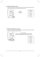
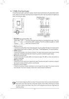
F_USB1/F_USB2 USB 2.0/1.1 Headers, F_USB30 USB 3.0/2.0 Header
 |
View all Gigabyte GA-B75M-D2V manuals
Add to My Manuals
Save this manual to your list of manuals |
Page 19 highlights
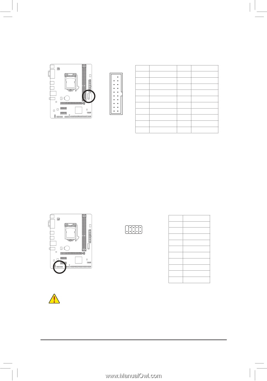
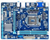
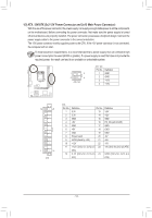
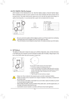
F_USB30 F_AUDIO(H) 11) F_USB30 (USB 3.0/2.0 Header) The header conforms to USB 3.0/2.0 specification and can provide two USB ports. For purchasing the optional 3.5" front panel that provides two USB 3.0/2.0 ports, please contact the local dealer. F_PANEL(NH) TPM w/housing 20 1 11 10 Pin No. Definition Pin No. 1 VBUS 11 2 SSRX1- 12 3 SSRX1+ 13 4 GND 14 DB5_PORTSSTX1- 15 6 SSTX1+ 16 7 GND 17 8 D1- 18 9 D1+ 19 Volta1g0e measNurCement module(X58A-O2C0) Definition D2+ D2GND SSBTIXO2S+Switcher (X58A-OC) SSTX2GND 1 SSRX2+ SSRX2VBUS No Pin PWM Switch (X58A-OC) M_SATA DIP 1 23 1 DIP 1 23 1 DIP 1 23 1 DIP 1 23 PCIe power connector (SATA)(X58A-OC) 12) F_USB1/F_USB2 (USB 2.0/1.1 Headers) The headers conform to USB 2.0/1.1 specification. Each USB header can provide two USB ports via an optional USB bracket. For purchasing the optional USB bracket, please contact the local dealer. Voltage measurement points(9G1.Sniper 3) 1 10 2 Pin No. Definition BIOS Switche1r (SW4) Power (5V) 2 Power (5V) 3 USB DX4 USB DY5 USB DX+ 6 USB DY+ 7 GND 8 GND 9 No Pin 10 NC •• Do not plug the IEEE 1394 bracket (2x5-pin) cable into the USB header. •• Prior to installing the USB bracket, be sure to turn off your computer and unplug the power cord from the power outlet to prevent damage to the USB bracket. - 19 -
-
 1
1 -
2
-
3
-
4
-
5
-
6
-
7
-
8
-
9
-
10
-
11
-
12
-
13
-
 14
14 -
 15
15 -
 16
16 -
 17
17 -
 18
18 -
 19
19 -
 20
20 -
 21
21 -
 22
22 -
 23
23 -
 24
24 -
25
-
26
-
27
-
28
-
29
-
30
-
31
-
32
-
33
-
34
-
35
-
36
-
37
-
38
-
39
-
40
-
41
-
42
-
43
-
44
 |
 |