Gigabyte GA-B75N Manual - Page 13
Center/Subwoofer Speaker Out Jack Orange, Rear Speaker Out Jack Black, Optical S/PDIF Out Connector
 |
View all Gigabyte GA-B75N manuals
Add to My Manuals
Save this manual to your list of manuals |
Page 13 highlights
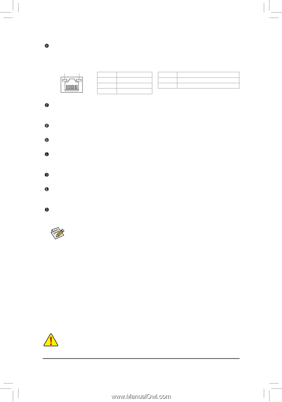
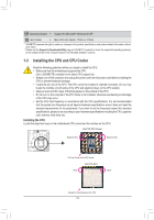
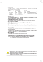
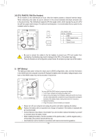
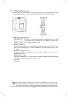
RJ-45 LAN Port The Gigabit Ethernet LAN port provides Internet connection at up to 1 Gbps data rate. The following describes the states of the LAN port LEDs. Connection/ Speed LED Activity LED LAN Port Connection/Speed LED: State Description Orange 1 Gbps data rate Green 100 Mbps data rate Off 10 Mbps data rate Activity LED: State Blinking Off Description Data transmission or receiving is occurring No data transmission or receiving is occurring USB 2.0/1.1 Port The USB port supports the USB 2.0/1.1 specification. Use this port for USB devices such as a USB keyboard/mouse, USB printer, USB flash drive and etc. Center/Subwoofer Speaker Out Jack (Orange) Use this audio jack to connect center/subwoofer speakers in a 5.1/7.1-channel audio configuration. Rear Speaker Out Jack (Black) Use this audio jack to connect rear speakers in a 4/5.1/7.1-channel audio configuration. Optical S/PDIF Out Connector This connector provides digital audio out to an external audio system that supports digital optical audio. Before using this feature, ensure that your audio system provides an optical digital audio in connector. Line In Jack (Blue) The default line in jack. Use this audio jack for line in devices such as an optical drive, walkman, etc. Line Out Jack (Green) The default line out jack. Use this audio jack for a headphone or 2-channel speaker. This jack can be used to connect front speakers in a 4/5.1/7.1-channel audio configuration. Mic In Jack (Pink) The default Mic in jack. Microphones must be connected to this jack. The audio jacks can be reconfigured to perform different functions via the audio software. If you install a Side Speaker, you need to retask other audio jack to be Side Speaker out. Only microphones still MUST be connected to the default Mic in jack. •• When removing the cable connected to a back panel connector, first remove the cable from your device and then remove it from the motherboard. •• When removing the cable, pull it straight out from the connector. Do not rock it side to side to prevent an electrical short inside the cable connector. - 13 -
-
 1
1 -
2
-
3
-
4
-
5
-
6
-
7
-
 8
8 -
 9
9 -
 10
10 -
 11
11 -
 12
12 -
 13
13 -
 14
14 -
 15
15 -
 16
16 -
 17
17 -
 18
18 -
19
-
20
-
21
-
22
-
23
-
24
-
25
-
26
-
27
-
28
-
29
-
30
-
31
-
32
-
33
-
34
-
35
-
36
-
37
-
38
-
39
-
40
-
41
-
42
-
43
-
44
 |
 |