Gigabyte GA-EP45-DS5 Manual - Page 27
GS0-Source/GS1/GS2-Source/GS3 SATA 3Gb/s Connectors, Controlled by GIGABYTE, SATA2/SiI5723, Purple,
 |
View all Gigabyte GA-EP45-DS5 manuals
Add to My Manuals
Save this manual to your list of manuals |
Page 27 highlights
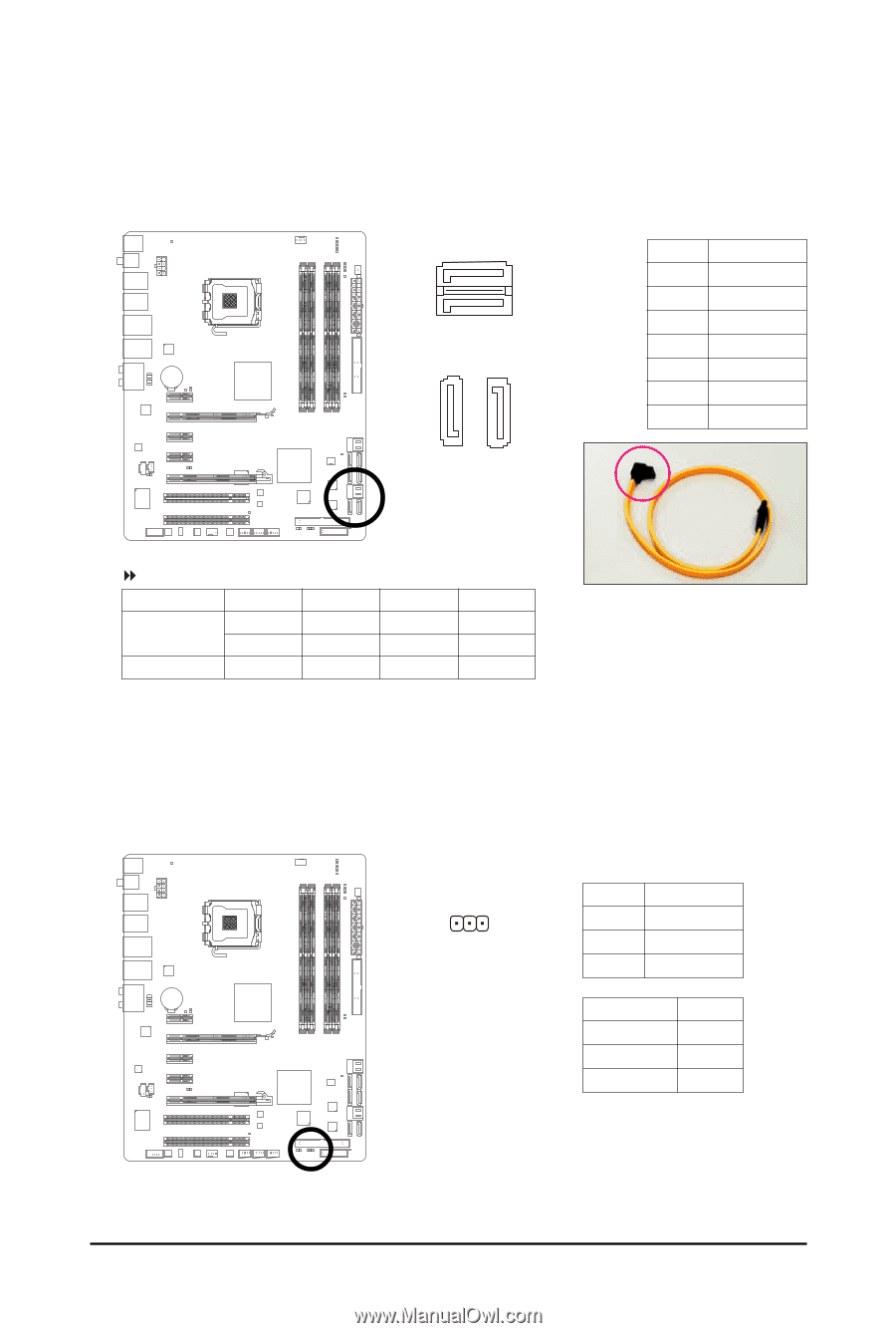
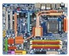
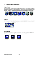
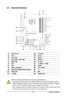
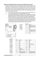
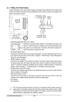
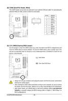
9) GS0-Source/GS1/GS2-Source/GS3 (SATA 3Gb/s Connectors, Controlled by GIGABYTE SATA2/SiI5723, Purple) The SATA connectors conform to SATA 3Gb/s standard and are compatible with SATA 1.5Gb/s standard. Each SATA connector supports a single SATA device. The GIGABYTE SATA2/SiI5723 controllers support Smart Backup Function. 7 7 1 GS3 1 GS1 GS0-Source 1 7 GS2-Source Pin No. 1 2 3 4 5 6 7 Definition GND TXP TXN GND RXN RXP GND 7 1 Smart Backup Function Configurations Table GS0-Source GS1 GS2-Source GS3 2 SATA hard drives V V X X X X V V 4 SATA hard drives V V V V Please connect the L-shaped end of the SATA 3Gb/s cable to your SATA hard drive. 10) PWR_LED (System Power LED Header) This header can be used to connect a system power LED on the chassis to indicate system power status. The LED is on when the system is operating. The LED keeps blinking when the system is in S1 sleep state. The LED is off when the system is in S3/S4 sleep state or powered off (S5). Pin No. Definition 1 1 MPD+ 2 MPD- 3 MPD- System Status LED S0 On S1 Blinking S3/S4/S5 Off - 27 - Hardware Installation
-
 1
1 -
2
-
3
-
4
-
5
-
6
-
7
-
8
-
9
-
10
-
11
-
12
-
13
-
14
-
15
-
16
-
17
-
18
-
19
-
20
-
21
-
 22
22 -
 23
23 -
 24
24 -
 25
25 -
 26
26 -
 27
27 -
 28
28 -
 29
29 -
 30
30 -
 31
31 -
 32
32 -
33
-
34
-
35
-
36
-
37
-
38
-
39
-
40
-
41
-
42
-
43
-
44
-
45
-
46
-
47
-
48
-
49
-
50
-
51
-
52
-
53
-
54
-
55
-
56
-
57
-
58
-
59
-
60
-
61
-
62
-
63
-
64
-
65
-
66
-
67
-
68
-
69
-
70
-
71
-
72
-
73
-
74
-
75
-
76
-
77
-
78
-
79
-
80
-
81
-
82
-
83
-
84
-
85
-
86
-
87
-
88
-
89
-
90
-
91
-
92
-
93
-
94
-
95
-
96
-
97
-
98
-
99
-
100
-
101
-
102
-
103
-
104
-
105
-
106
-
107
-
108
-
109
-
110
-
111
-
112
-
113
-
114
-
115
-
116
 |
 |