Gigabyte GA-G31-S3G Manual
Gigabyte GA-G31-S3G Manual
 |
View all Gigabyte GA-G31-S3G manuals
Add to My Manuals
Save this manual to your list of manuals |
Gigabyte GA-G31-S3G manual content summary:
- Gigabyte GA-G31-S3G | Manual - Page 1
GA-G31-S3G LGA775 socket motherboard for Intel® CoreTM processor family/ Intel® Pentium® processor family/Intel® Celeron® processor family User's Manual Rev. 1001 12ME-G31S3G-1001R - Gigabyte GA-G31-S3G | Manual - Page 2
Motherboard GA-G31-S3G Feb. 9, 2009 Motherboard GA-G31-S3G Feb. 9, 2009 - Gigabyte GA-G31-S3G | Manual - Page 3
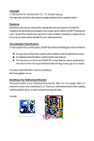
with the product. For detailed product information, carefully read the User's Manual. For instructions on how to use GIGABYTE's unique features, read or download the information on/from the Support\Motherboard\Technology Guide page on our website. For product-related information, check on our - Gigabyte GA-G31-S3G | Manual - Page 4
GA-G31-S3G Motherboard Layout 7 Block Diagram ...8 Chapter 1 Hardware Installation 9 1-1 Installation Precautions 9 1-2 Product Specifications 10 1-3 Installing the CPU and CPU Cooler 13 1-3-1 Installing the CPU 13 1-3-2 Installing the CPU Features 38 2-5 Advanced BIOS Features 40 2-6 - Gigabyte GA-G31-S3G | Manual - Page 5
Chipset Drivers 55 3-2 Application Software 56 3-3 Technical Manuals 56 3-4 Contact ...57 3-5 System ...57 3-6 Download Center 58 Chapter 4 Unique Features 59 4-1 Xpress Recovery2 59 4-2 BIOS Update Utilities 62 4-2-1 Updating the BIOS with the Q-Flash Utility 62 4-2-2 Updating the BIOS with - Gigabyte GA-G31-S3G | Manual - Page 6
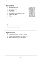
Box Contents GA-G31-S3G motherboard Motherboard driver disk User's Manual Quick Installation Guide One IDE cable and one floppy disk drive cable Two SATA 3Gb/s cables I/O Shield • The box contents above are for reference only and the actual - Gigabyte GA-G31-S3G | Manual - Page 7
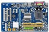
GA-G31-S3G Motherboard Layout KB_MS ATX_12V LGA775 CPU_FAN VGA COMA LPT USB R_USB LAN GA-G31-S3G ATX IDE AUDIO F_AUDIO RTL8111C IT8718 CODEC PCIE_1 PCIE_16 PCIE_2 PCIE_3 CD_IN SPDIF_O PCI1 PCI2 PCI3 Intel® G31 BATTERY Intel® ICH7 SATAII2 SATAII3 CLR_CMOS F_USB1 F_USB2 SATAII0 MBIOS - Gigabyte GA-G31-S3G | Manual - Page 8
Express x16 3 PCI Express x1 LGA775 Processor Host Interface Intel® G31 CPU CLK+/(333/266/200 MHz) DDR2 1066/800/667 MHz Dual Channel MHz) x1 x1 x1 PCI Express Bus RTL8111C RJ45 LAN PCI Bus Intel® ICH7 CODEC BIOS ATA-100/66/33 IDE Channel 4 SATA 3Gb/s 8 USB Ports IT8718 Floppy LPT Port - Gigabyte GA-G31-S3G | Manual - Page 9
manual and follow these procedures: • Prior to installation, do not remove or break motherboard S/N (ESD) wrist strap when handling electronic components such as a motherboard, CPU or memory. If you do not have an ESD wrist steps or have a problem related to the use of the product, please consult - Gigabyte GA-G31-S3G | Manual - Page 10
supporting up to 4 SATA 3Gb/s devices iTE IT8718 chip: - 1 x floppy disk drive connector supporting up to 1 floppy disk drive Integrated in the South Bridge Up to 8 USB 2.0/1.1 ports (4 on the back panel, 4 via the USB brackets connected to the internal USB headers) GA-G31-S3G Motherboard - Gigabyte GA-G31-S3G | Manual - Page 11
x SATA 3Gb/s connectors 1 x CPU fan header 1 x system fan CPU temperature detection CPU/System fan speed detection CPU overheating warning CPU/System fan fail warning CPU fan speed control(Note 2) BIOS 1 x 4 Mbit flash Use of licensed AWARD BIOS PnP 1.0a, DMI 2.0, SM BIOS - Gigabyte GA-G31-S3G | Manual - Page 12
example, 4 GB of memory size will instead be shown as 3.xx GB during system startup. (Note 2) Whether the CPU fan speed control function is supported will depend on the CPU cooler you install. (Note 3) Available functions in EasyTune may differ by motherboard model. GA-G31-S3G Motherboard - 12 - - Gigabyte GA-G31-S3G | Manual - Page 13
before you begin to install the CPU: • Make sure that the motherboard supports the CPU. (Go to GIGABYTE's website for the latest CPU support list.) • Always turn off the computer and unplug the power cord from the power outlet before installing the CPU to prevent hardware damage. • Locate the - Gigabyte GA-G31-S3G | Manual - Page 14
pin one corner of the CPU socket (or you may align the CPU notches with the socket alignment keys) and gently insert the CPU into position. Step 5: Once the CPU is properly inserted, replace the load plate and push the CPU socket lever back into its locked position. GA-G31-S3G Motherboard - 14 - - Gigabyte GA-G31-S3G | Manual - Page 15
. Check that the Male and Female push pins are joined closely. (Refer to your CPU cooler installation manual for instructions on installing the cooler.) Step 5: After the installation, check the back of the motherboard. If the push pin is inserted as the picture above, the installation is complete - Gigabyte GA-G31-S3G | Manual - Page 16
Make sure that the motherboard supports the memory. It is recommended that memory of the same capacity, brand, speed, and chips be used. (Go to GIGABYTE's website for the latest memory support list.) • Always turn of the same capacity, brand, speed, and chips be used. GA-G31-S3G Motherboard - 16 - - Gigabyte GA-G31-S3G | Manual - Page 17
power outlet to prevent damage to the memory module. DDR2 DIMMs are not compatible to DDR DIMMs. Be sure to install DDR2 DIMMs on this motherboard. Notch DDR2 DIMM A DDR2 memory module has a notch, so it can only fit in one direction. Follow the steps below to correctly install your memory - Gigabyte GA-G31-S3G | Manual - Page 18
expansion card: • Make sure the motherboard supports the expansion card. Carefully read the manual that came with your expansion card. necessary, go to BIOS Setup to make any required BIOS changes for your expansion card(s). 7. Install the driver provided with the GA-G31-S3G Motherboard - 18 - - Gigabyte GA-G31-S3G | Manual - Page 19
D-Sub port supports a 15-pin D-Sub connector. Connect a monitor that supports D-Sub connection to this port. USB Port The USB port supports the USB first remove the cable from your device and then remove it from the motherboard. • When removing the cable, pull it straight out from the connector. - Gigabyte GA-G31-S3G | Manual - Page 20
speakers in a 4/5.1-channel audio configuration. Mic In Jack (Pink) The default Mic in jack. Microphones must be connected to this jack. Refer to the instructions on setting up a 2/4/5.1-channel audio configuration in Chapter 5, "Configuring 2/4/5.1-Channel Audio." GA-G31-S3G Motherboard - 20 - - Gigabyte GA-G31-S3G | Manual - Page 21
devices. • After installing the device and before turning on the computer, make sure the device cable has been securely attached to the connector on the motherboard. - 21 - Hardware Installation - Gigabyte GA-G31-S3G | Manual - Page 22
cable to the power connector in the correct orientation. The 12V power connector mainly supplies power to the CPU. If the 12V power connector is not connected, the computer will not start. • To meet expansion +5V +5V (Only for 2x12-pin ATX) GND (Only for 2x12-pin ATX) GA-G31-S3G Motherboard - 22 - - Gigabyte GA-G31-S3G | Manual - Page 23
fan cable, be sure to connect it in the correct orientation (the black connector wire is the ground wire). The motherboard supports CPU fan speed control, which requires the use of a CPU fan with fan speed control design. For optimum heat dissipation, it is recommended that a system fan be installed - Gigabyte GA-G31-S3G | Manual - Page 24
configuring master/slave settings for the IDE devices, read the instructions from the device manufacturers.) 40 39 2 1 7) SATAII0 supports a single SATA device. SATAII2 7 1 1 7 SATAII3 SATAII0 7 1 Pin No. 1 2 3 4 5 6 7 Definition GND TXP TXN GND RXN RXP GND GA-G31-S3G Motherboard - Gigabyte GA-G31-S3G | Manual - Page 25
pin assignments of the motherboard header. Incorrect connection between the module connector and the motherboard header will make the device supports HD audio by default. If your chassis provides an AC'97 front panel audio module, refer to the instructions on how to activate AC'97 functionality via - Gigabyte GA-G31-S3G | Manual - Page 26
heard if no problem is detected at system startup. If a problem is detected, the BIOS may issue beeps in different patterns to indicate the problem. Refer to Chapter 5, "Troubleshooting," for information about assignments and the pin assignments are matched correctly. GA-G31-S3G Motherboard - 26 - - Gigabyte GA-G31-S3G | Manual - Page 27
No. Definition 1 1 CD-L 2 GND 3 GND 4 CD-R 12) SPDIF_O (S/PDIF Out Header) This header supports digital S/PDIF out. Via an optional S/PDIF out cable, this header can connect to an audio device that supports digital audio in. For purchasing the optional S/PDIF out cable, please contact the - Gigabyte GA-G31-S3G | Manual - Page 28
can provide two USB ports via an optional USB bracket. For motherboard. • After system restart, go to BIOS Setup to load factory defaults (select Load Optimized Defaults) or manually configure the BIOS settings (refer to Chapter 2, "BIOS Setup," for BIOS configurations). GA-G31-S3G Motherboard - Gigabyte GA-G31-S3G | Manual - Page 29
) This motherboard provides a chassis detection feature that detects if the chassis cover has been removed. This function requires a chassis with chassis intrusion detection design. Pin No. Definition 1 Signal 1 2 GND 16) BATTERY The battery provides power to keep the values (such as BIOS - Gigabyte GA-G31-S3G | Manual - Page 30
GA-G31-S3G Motherboard - 30 - - Gigabyte GA-G31-S3G | Manual - Page 31
that searches and downloads the latest version of BIOS from the Internet and updates the BIOS. For instructions on using the Q-Flash and @BIOS utilities, refer to Chapter 4, "BIOS Update Utilities." • Because BIOS flashing is potentially risky, if you do not encounter problems using the current - Gigabyte GA-G31-S3G | Manual - Page 32
, the device boot order will still be based on BIOS Setup settings. You can access Boot Menu again to change the first boot device setting as needed. : Q-Flash Press the key to access the Q-Flash utility directly without having to enter BIOS Setup first. GA-G31-S3G Motherboard - 32 - - Gigabyte GA-G31-S3G | Manual - Page 33
Save & Exit Setup F11: Save CMOS to BIOS F12: Load CMOS from BIOS Change CPU's Clock & Voltage BIOS Setup Program Function Keys Move the selection bar to Display system information Save all the changes and exit the BIOS Setup program Save CMOS to BIOS Load CMOS from BIOS - Gigabyte GA-G31-S3G | Manual - Page 34
CMOS and exit BIOS Setup. (Pressing can also carry out this task.) Exit Without Saving Abandon all changes and the previous settings remain in effect. Pressing to the confirmation message will exit BIOS Setup. (Pressing can also carry out this task.) GA-G31-S3G Motherboard - 34 - - Gigabyte GA-G31-S3G | Manual - Page 35
) Allows you to increases clock ratio by 0.5 for the installed CPU. The item is present only if a CPU with unlocked clock ratio is installed. CPU Frequency Displays the current operating CPU frequency. (Note) This item appears only if you install a CPU that supports this feature. - 35 - BIOS Setup - Gigabyte GA-G31-S3G | Manual - Page 36
CPU Host Frequency (Mhz) and System Memory Multiplier settings. ******** System Voltage Optimized ******** System Voltage Control Determines whether to manually set the system voltages. Auto lets BIOS +0.3V Increases PCIe bus voltage by 0.1V to 0.3V at 0.1V increment. GA-G31-S3G Motherboard - 36 - - Gigabyte GA-G31-S3G | Manual - Page 37
the CPU voltage as required. The adjustable range is dependent on the CPU being installed. (Default: Normal) Note: Increasing CPU voltage may result in damage to your CPU or reduce the useful life of the CPU. Normal CPU Vcore Displays the normal operating voltage of your CPU. - 37 - BIOS Setup - Gigabyte GA-G31-S3G | Manual - Page 38
] [None] [None] [None] [None] Drive A Floppy 3 Mode Support [1.44M, 3.5"] [Disabled] Halt On [All, But Keyboard] Base Memory one of the three methods below: • Auto • None • Manual Lets BIOS automatically detect IDE/SATA devices during the POST. (Default) If GA-G31-S3G Motherboard - 38 - - Gigabyte GA-G31-S3G | Manual - Page 39
display your hard drive specifications. If you wish to enter the parameters manually 720K/3.5", 1.44M/3.5", 2.88M/3.5". Floppy 3 Mode Support Allows you to specify whether the installed floppy disk stop for any error. All Errors Whenever the BIOS detects a non-fatal error the system boot will - Gigabyte GA-G31-S3G | Manual - Page 40
CPU Enhanced Halt (C1E) (Note) CPU Thermal Monitor 2(TM2) (Note) CPU EIST Function (Note) Virtualization Technology (Note) Full Screen LOGO Show Init Display CPU that supports this feature. For more information about Intel CPUs' unique features, please visit Intel's website. GA-G31-S3G Motherboard - Gigabyte GA-G31-S3G | Manual - Page 41
display the GIGABYTE Logo at system startup. Disabled displays normal POST message. (Default: Enabled) Init Display First Specifies the first initiation of the monitor display present only if you install a CPU that supports this feature. For more information about Intel CPUs' unique features, please - Gigabyte GA-G31-S3G | Manual - Page 42
On-Chip Frame Buffer Size Frame buffer size is the total amount of system memory allocated solely for the onboard graphics controller. MS-DOS, for example, will use only this memory for display. Options are: 8MB+1~2MB for GTT (default), 1MB+1~2MB for GTT. GA-G31-S3G Motherboard - 42 - - Gigabyte GA-G31-S3G | Manual - Page 43
to USB Controller USB 2.0 Controller USB Keyboard Support USB Mouse Support Legacy USB storage detect Azalia Codec Onboard H/W SATA controller. Auto Lets BIOS set SATA devices to Combined automatically configured to Combined mode, you can manually re-configure it to Enhanced mode as needed - Gigabyte GA-G31-S3G | Manual - Page 44
: Enabled) USB Keyboard Support Allows USB keyboard to be used in MS-DOS. (Default: Disabled) USB Mouse Support Allows USB mouse to be motherboard, the Status fields of all four pairs of wires will show Open and the Length fields show 0m, as shown in the figure above. GA-G31-S3G Motherboard - Gigabyte GA-G31-S3G | Manual - Page 45
problem is detected on the LAN cable connected to a Gigabit hub or a 10/100 Mbps hub, the following message will appear: Start detecting at Port..... Link Detected --> 100Mbps Cable Length= 30m Link Detected Cable Length Displays transmission speed Displays Port), ECP+EPP. - 45 - BIOS Setup - Gigabyte GA-G31-S3G | Manual - Page 46
Resume by Alarm x Date (of Month) Alarm x Time (hh:mm:ss) Alarm HPET Support (Note) HPET Mode (Note) Power On By Mouse Power On By Keyboard x KB Power a modem that supports wake-up function. (Default: Enabled) (Note) Supported on Windows® Vista® operating system only. GA-G31-S3G Motherboard - 46 - - Gigabyte GA-G31-S3G | Manual - Page 47
the operating system or removal of the AC power, or the settings may not be effective. HPET Support (Note) Enables or disables High Precision Event Timer (HPET) for Windows® Vista® operating system. upon the return of the AC power. (Note) Supported on Windows® Vista® operating system only. - 47 - Gigabyte GA-G31-S3G | Manual - Page 48
,14,15 to the first PCI slot. BIOS auto-assigns IRQ to the second PCI slot. (Default) Assigns IRQ 3,4,5,7,9,10,11,12,14,15 to the second PCI slot. BIOS auto-assigns IRQ to the third PCI slot. (Default) Assigns IRQ 3,4,5,7,9,10,11,12,14,15 to the third PCI slot. GA-G31-S3G Motherboard - 48 - - Gigabyte GA-G31-S3G | Manual - Page 49
system voltages. Current CPU Temperature Displays current CPU temperature. Current CPU/SYSTEM FAN Speed (RPM) Displays current CPU/system fan speed. CPU Warning Temperature Sets the warning threshold for CPU temperature. When CPU temperature exceeds the threshold, BIOS will emit warning sound - Gigabyte GA-G31-S3G | Manual - Page 50
or disables the CPU fan speed control function. Enabled allows the CPU fan to run at different speed according to the CPU temperature. You can adjust the fan speed with EasyTune based on system requirements. If disabled, CPU fan runs at full speed. (Default: Enabled) GA-G31-S3G Motherboard - 50 - - Gigabyte GA-G31-S3G | Manual - Page 51
stable BIOS settings for the motherboard. BIOS Load Optimized Defaults Press on this item and then press the key to load the optimal BIOS default settings. The BIOS defaults settings help the system to operate in optimum state. Always load the Optimized defaults after updating the BIOS - Gigabyte GA-G31-S3G | Manual - Page 52
allows you to view the BIOS settings but not to make changes. To clear the password, press on the password item and when requested for the password, press again. The message "PASSWORD DISABLED" will appear, indicating the password has been cancelled. GA-G31-S3G Motherboard - 52 - - Gigabyte GA-G31-S3G | Manual - Page 53
PnP/PCI Configurations Exit Without Saving PC Health Status ESC: Quit F8: Q-Flash Select Item F10: Save & Exit Setup F11: Save CMOS to BIOS F12: Load CMOS from BIOS Save Data to CMOS Press on this item and press the key. This saves the changes to the CMOS and exits the - Gigabyte GA-G31-S3G | Manual - Page 54
GA-G31-S3G Motherboard - 54 - - Gigabyte GA-G31-S3G | Manual - Page 55
other drivers. • After the drivers are installed, follow the onscreen instructions to restart your system. You can install other applications included in the motherboard driver disk. • For USB 2.0 driver support under the Windows XP operating system, please install the Windows XP Service Pack - Gigabyte GA-G31-S3G | Manual - Page 56
that GIGABYTE develops and some free software. You can click the Install button on the right of an item to install it. 3-3 Technical Manuals This page provides GIGABYTE's application guides, content descriptions for this driver disk, and the motherboard manuals. GA-G31-S3G Motherboard - 56 - Gigabyte GA-G31-S3G | Manual - Page 57
3-4 Contact For the detailed contact information of the GIGABYTE Taiwan headquarter or worldwide branch offices, click the URL on this page to link to the GIGABYTE website. 3-5 System This page provides the basic system information. - 57 - Drivers Installation - Gigabyte GA-G31-S3G | Manual - Page 58
3-6 Download Center To update the BIOS, drivers, or applications, click the Download Center button to link to the GIGABYTE Web site. The latest version of the BIOS, drivers, or applications will be displayed. GA-G31-S3G Motherboard - 58 - - Gigabyte GA-G31-S3G | Manual - Page 59
compress and back up your system data and perform restoration of it. Supporting NTFS, FAT32, and FAT16 file systems, Xpress Recovery2 can back up is recommended to back up your system soon after the operating system and drivers are installed. • The amount of data and hard drive access speed may affect - Gigabyte GA-G31-S3G | Manual - Page 60
Xpress Recovery2 cannot save the backup file. B. Accessing Xpress Recovery2 1. Boot from the motherboard driver disk to access Xpress Recovery2 for the first time. When you see the following message: 2: When finished, go to Disk Management to check disk allocation. GA-G31-S3G Motherboard - 60 - - Gigabyte GA-G31-S3G | Manual - Page 61
D. Using the Restore Function in Xpress Recovery2 Select RESTORE to restore the backup to your hard drive in case the system breaks down. The RESTORE option will not be present if no backup is created before. E. Removing the Backup Step 1: If you wish to remove the backup file, select REMOVE. F. - Gigabyte GA-G31-S3G | Manual - Page 62
Windows environment. @BIOS will download the latest BIOS file from the nearest @BIOS server site and update the BIOS. 4-2-1 Updating the BIOS with the Q-Flash Utility A. Before You Begin: 1. From GIGABYTE's website, download the latest compressed BIOS update file that matches your motherboard model - Gigabyte GA-G31-S3G | Manual - Page 63
the BIOS update file matches your motherboard model. Step 2: The process of the system reading the BIOS file from the floppy disk is displayed on the screen. When the message "Are you sure to update BIOS?" appears, press to begin the BIOS update. The monitor will display the update process - Gigabyte GA-G31-S3G | Manual - Page 64
Setup F11: Save CMOS to BIOS F12: Load CMOS from BIOS Load Optimized Defaults Press to load BIOS defaults Step 6: Select Save & Exit Setup and then press to save settings to CMOS and exit BIOS Setup. The procedure is complete after the system restarts. GA-G31-S3G Motherboard - 64 - - Gigabyte GA-G31-S3G | Manual - Page 65
to your location and then download the BIOS file that matches your motherboard model. Follow the onscreen instructions to complete. If the BIOS update file for your motherboard is not present on the @BIOS server site, please manually download the BIOS update file from GIGABYTE's website and follow - Gigabyte GA-G31-S3G | Manual - Page 66
hardware monitoring and warning. (For instructions on using EasyTune5 Pro, read or download the information on/from the Support\Motherboard\Utility page on our website.) The EasyTune 5 Pro Interface Button Information Table Button/Display 1. OVERCLOCKING 2. C.I.A./M.I.B. 3. SMART FAN 4. PC HEALTH - Gigabyte GA-G31-S3G | Manual - Page 67
Configuring 2/4/5.1-Channel Audio The motherboard provides three audio jacks on the back panel which support 2/4/5.1-channel(Note) audio. Speakers: (The following instructions use Windows Vista as the example operating system.) Step 1: After installing the audio driver, the HD Audio Manager - Gigabyte GA-G31-S3G | Manual - Page 68
icon on the Speaker Configuration tab. On the Connector Settings dialog box, select the Disable front panel jack detection check box. Click OK to complete. GA-G31-S3G Motherboard - 68 - - Gigabyte GA-G31-S3G | Manual - Page 69
external decoder. A. Installing the S/PDIF Out Cable: Step 1: First, attach the connector at the end of the cable to the SPDIF_O header on your motherboard. Pin 1 (the red wire) of the S/PDIF out cable must align with pin 1 of the SPDIF_O header. Incorrect connection may render the device unusable - Gigabyte GA-G31-S3G | Manual - Page 70
S/PDIF Out: On the Digital Output screen, click the Default Format tab and then select the sample rate and bit depth. Click OK to complete. GA-G31-S3G Motherboard - 70 - - Gigabyte GA-G31-S3G | Manual - Page 71
5-1-3 Configuring Microphone Recording Step 1: After installing the audio driver, the HD Audio Manager icon will appear in the notification area. Doubleclick the icon to access the HD Audio Manager. Step 2: Connect your microphone to - Gigabyte GA-G31-S3G | Manual - Page 72
Sound Recorder to begin the sound recording. * Enabling Stereo Mix If the HD Audio Manager does not display the recording device you wish to use, refer to the steps below. The following steps explain how right-click on an empty space and select Show Disabled Devices. GA-G31-S3G Motherboard - 72 - - Gigabyte GA-G31-S3G | Manual - Page 73
. Be sure to save the recorded audio file upon completion. B. Playing the Recorded Sound: You can play your recording in a digital media player program that supports your audio file format. - 73 - Appendix - Gigabyte GA-G31-S3G | Manual - Page 74
5-2 Troubleshooting 5-2-1 Frequently Asked Questions To read more FAQs for your motherboard, please go to the Support\Motherboard\FAQ page on GIGABYTE's website. Q: In the BIOS Setup program, why are some BIOS options missing? A: Some advanced options are hidden in the BIOS Setup program. Press < - Gigabyte GA-G31-S3G | Manual - Page 75
Procedure If you encounter any troubles during system startup, follow the troubleshooting procedure below to solve the problem. START Turn off the power. Remove all peripherals, connecting cables, and power cord etc. Make sure the motherboard does not short-circuit with the chassis or - Gigabyte GA-G31-S3G | Manual - Page 76
and solved. END If the procedure above is unable to solve your problem, contact the place of purchase or local dealer for help. Or go to the Support\Technical Service Zone page to submit your question. Our customer service staff will reply you as soon as possible. GA-G31-S3G Motherboard - 76 - - Gigabyte GA-G31-S3G | Manual - Page 77
GIGABYTE. Our Commitment to Preserving the Environment In addition to high-efficiency performance, all GIGABYTE motherboards local government office, your household waste disposal service or where you purchased the product for user's manual and we will be glad to help you with your effort. - - Gigabyte GA-G31-S3G | Manual - Page 78
disposed of properly. China Restriction of Hazardous Substances Table The following table is supplied in compliance with China's Restriction of Hazardous Substances (China RoHS) requirements: GA-G31-S3G Motherboard - 78 - - Gigabyte GA-G31-S3G | Manual - Page 79
- 79 - Appendix - Gigabyte GA-G31-S3G | Manual - Page 80
GA-G31-S3G Motherboard - 80 - - Gigabyte GA-G31-S3G | Manual - Page 81
- 81 - Appendix - Gigabyte GA-G31-S3G | Manual - Page 82
GA-G31-S3G Motherboard - 82 - - Gigabyte GA-G31-S3G | Manual - Page 83
231, Taiwan TEL: +886-2-8912-4000 FAX: +886-2-8912-4003 Tech. and Non-Tech. Support (Sales/Marketing) : http://ggts.gigabyte.com.tw WEB address (English): http://www.gigabyte.com.tw WEB address (Chinese): http://www.gigabyte.tw G.B.T. INC. - U.S.A. TEL: +1-626-854-9338 FAX: +1-626-854-9339 Tech - Gigabyte GA-G31-S3G | Manual - Page 84
your language in the language list on the top right corner of the website. GIGABYTE Global Service System To submit a technical or non-technical (Sales/ Marketing) question, please link to : http://ggts.gigabyte.com.tw Then select your language to enter the system. GA-G31-S3G Motherboard - 84 -
-
 1
1 -
 2
2 -
 3
3 -
 4
4 -
 5
5 -
 6
6 -
 7
7 -
8
-
9
-
10
-
11
-
12
-
13
-
14
-
15
-
16
-
17
-
18
-
19
-
20
-
21
-
22
-
23
-
24
-
25
-
26
-
27
-
28
-
29
-
30
-
31
-
32
-
33
-
34
-
35
-
36
-
37
-
38
-
39
-
40
-
41
-
42
-
43
-
44
-
45
-
46
-
47
-
48
-
49
-
50
-
51
-
52
-
53
-
54
-
55
-
56
-
57
-
58
-
59
-
60
-
61
-
62
-
63
-
64
-
65
-
66
-
67
-
68
-
69
-
70
-
71
-
72
-
73
-
74
-
75
-
76
-
77
-
78
-
79
-
80
-
81
-
82
-
83
-
84
 |
 |

GA-G31-S3G
LGA775 socket motherboard for Intel
®
Core
TM
processor family/
Intel
®
Pentium
®
processor family/Intel
®
Celeron
®
processor family
User's Manual
Rev. 1001
12ME-G31S3G-1001R