Gigabyte GA-G31-S3G Manual - Page 25
PWR_LED System Power LED Header, F_AUDIO, Front Panel Audio Header
 |
View all Gigabyte GA-G31-S3G manuals
Add to My Manuals
Save this manual to your list of manuals |
Page 25 highlights
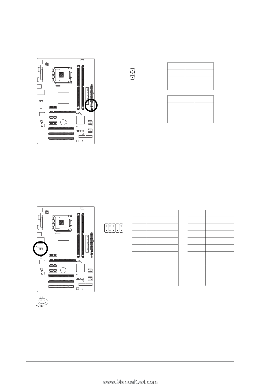
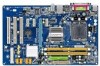
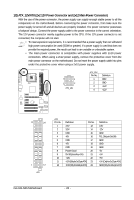
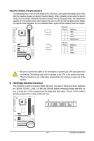
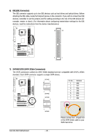
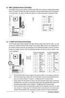
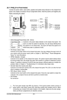
8) PWR_LED (System Power LED Header) This header can be used to connect a system power LED on the chassis to indicate system power status. The LED is on when the system is operating. The LED keeps blinking when the system is in S1 sleep state. The LED is off when the system is in S3/S4 sleep state or powered off (S5). Pin No. Definition 1 MPD+ 2 MPD- 1 3 MPD- System Status LED S0 On S1 Blinking S3/S4/S5 Off 9) F_AUDIO (Front Panel Audio Header) The front panel audio header supports Intel High Definition audio (HD) and AC'97 audio. You may connect your chassis front panel audio module to this header. Make sure the wire assignments of the module connector match the pin assignments of the motherboard header. Incorrect connection between the module connector and the motherboard header will make the device unable to work or even damage it. For HD Front Panel Audio: Pin No. Definition For AC'97 Front Panel Audio: Pin No. Definition 2 10 1 MIC2_L 2 GND 1 MIC 2 GND 1 9 3 MIC2_R 4 -ACZ_DET 3 MIC Power 4 NC 5 LINE2_R 5 Line Out (R) 6 FAUDIO_JD 6 NC 7 GND 7 NC 8 No Pin 8 No Pin 9 LINE2_L 9 Line Out (L) 10 FAUDIO_JD 10 NC • The front panel audio header supports HD audio by default. If your chassis provides an AC'97 front panel audio module, refer to the instructions on how to activate AC'97 functionality via the audio software in Chapter 5, "Configuring 2/4/5.1-Channel Audio." • Audio signals will be present on both of the front and back panel audio connections simultaneously. If you want to mute the back panel audio (only supported when using an HD front panel audio module), refer to Chapter 5, "Configuring 2/4/5.1-Channel Audio." • Some chassis provide a front panel audio module that has separated connectors on each wire instead of a single plug. For information about connecting the front panel audio module that has different wire assignments, please contact the chassis manufacturer. - 25 - Hardware Installation
-
 1
1 -
2
-
3
-
4
-
5
-
6
-
7
-
8
-
9
-
10
-
11
-
12
-
13
-
14
-
15
-
16
-
17
-
18
-
19
-
 20
20 -
 21
21 -
 22
22 -
 23
23 -
 24
24 -
 25
25 -
 26
26 -
 27
27 -
 28
28 -
 29
29 -
 30
30 -
31
-
32
-
33
-
34
-
35
-
36
-
37
-
38
-
39
-
40
-
41
-
42
-
43
-
44
-
45
-
46
-
47
-
48
-
49
-
50
-
51
-
52
-
53
-
54
-
55
-
56
-
57
-
58
-
59
-
60
-
61
-
62
-
63
-
64
-
65
-
66
-
67
-
68
-
69
-
70
-
71
-
72
-
73
-
74
-
75
-
76
-
77
-
78
-
79
-
80
-
81
-
82
-
83
-
84
 |
 |