Gigabyte GA-G31-S3G Manual - Page 27
CD_IN CD In Connector, SPDIF_O S/PDIF Out Header
 |
View all Gigabyte GA-G31-S3G manuals
Add to My Manuals
Save this manual to your list of manuals |
Page 27 highlights
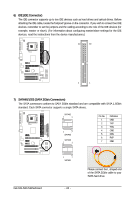
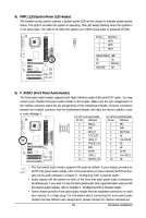
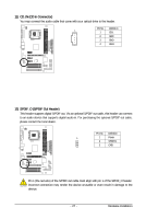
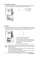
11) CD_IN (CD In Connector) You may connect the audio cable that came with your optical drive to the header. Pin No. Definition 1 1 CD-L 2 GND 3 GND 4 CD-R 12) SPDIF_O (S/PDIF Out Header) This header supports digital S/PDIF out. Via an optional S/PDIF out cable, this header can connect to an audio device that supports digital audio in. For purchasing the optional S/PDIF out cable, please contact the local dealer. Pin No. Definition 1 1 Power 2 SPDIFO 3 GND Pin 1 (the red wire) of the S/PDIF out cable must align with pin 1 of the SPDIF_O header. Incorrect connection may render the device unusable or even result in damage to the device. - 27 - Hardware Installation
-
 1
1 -
2
-
3
-
4
-
5
-
6
-
7
-
8
-
9
-
10
-
11
-
12
-
13
-
14
-
15
-
16
-
17
-
18
-
19
-
20
-
21
-
 22
22 -
 23
23 -
 24
24 -
 25
25 -
 26
26 -
 27
27 -
 28
28 -
 29
29 -
 30
30 -
 31
31 -
 32
32 -
33
-
34
-
35
-
36
-
37
-
38
-
39
-
40
-
41
-
42
-
43
-
44
-
45
-
46
-
47
-
48
-
49
-
50
-
51
-
52
-
53
-
54
-
55
-
56
-
57
-
58
-
59
-
60
-
61
-
62
-
63
-
64
-
65
-
66
-
67
-
68
-
69
-
70
-
71
-
72
-
73
-
74
-
75
-
76
-
77
-
78
-
79
-
80
-
81
-
82
-
83
-
84
 |
 |

Hardware Installation
- 27 -
11)
CD_IN (CD In Connector)
You may connect the audio cable that came with your optical drive to the header.
Pin No.
Definition
1
CD-L
2
GND
3
GND
4
CD-R
1
1
Pin No.
Definition
1
Power
2
SPDIFO
3
GND
12)
SPDIF_O (S/PDIF Out Header)
This header supports digital S/PDIF out. Via an optional S/PDIF out cable, this header can connect
to an audio device that supports digital audio in. For purchasing the optional S/PDIF out cable,
please contact the local dealer.
Pin 1 (the red wire) of the S/PDIF out cable must align with pin 1 of the SPDIF_O header.
Incorrect connection may render the device unusable or even result in damage to the
device.