Gigabyte GA-J1800N-D2P User Manual - Page 13
BAT Battery, SATA2 0/1 SATA 3Gb/s Connectors, CLR_CMOS Clear CMOS Jumper, CI Chassis Intrusion Header
 |
View all Gigabyte GA-J1800N-D2P manuals
Add to My Manuals
Save this manual to your list of manuals |
Page 13 highlights
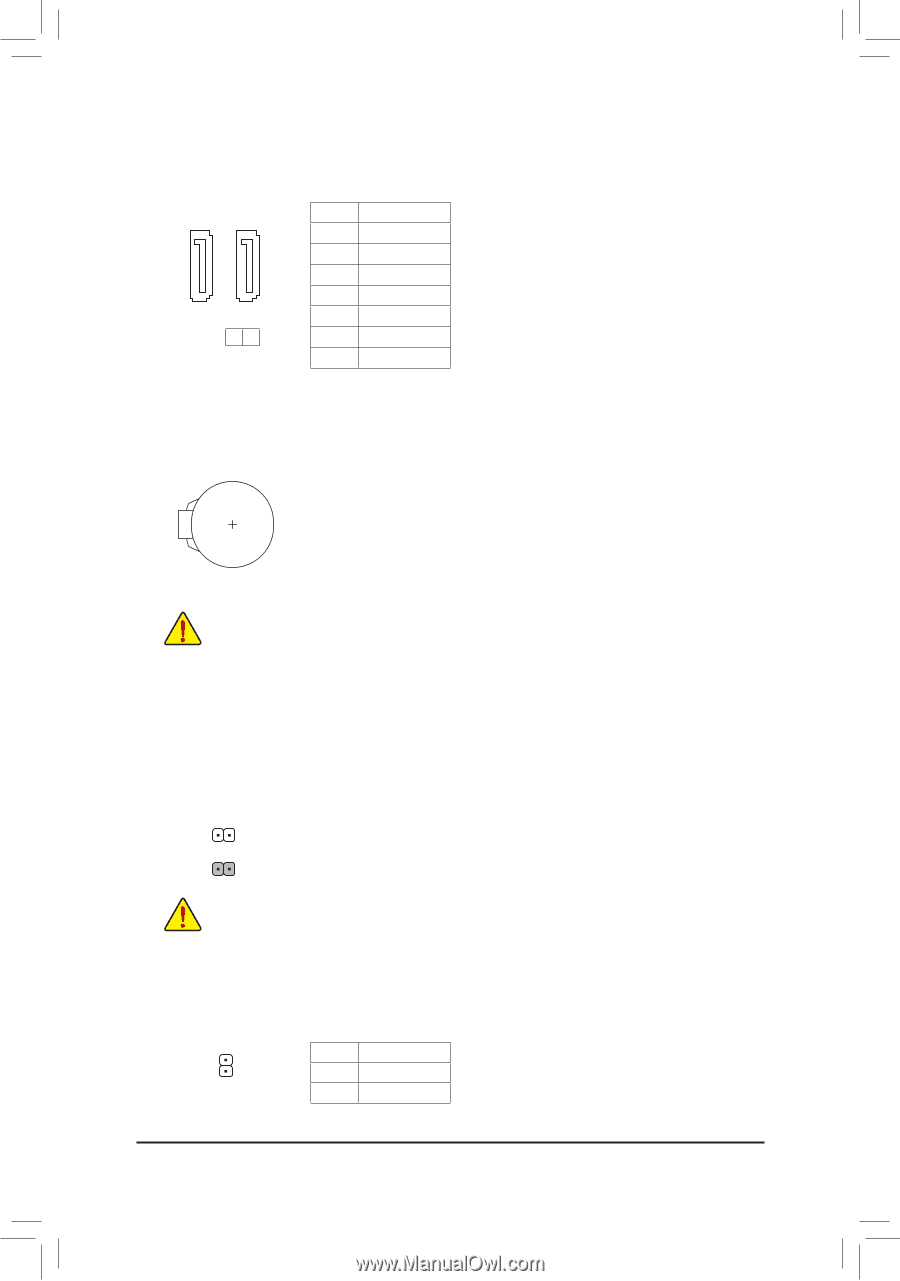
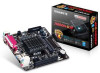
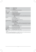
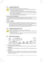
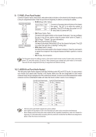
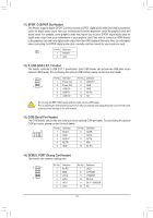
5) SATA2 0/1 (SATA 3Gb/s Connectors) The SATA connectors conform to SATA 3Gb/s standard and are compatible with SATA 1.5Gb/s standard. Each SATA connector supports a single SATA device. 7 7 1 1 SATA2 0 1 Pin No. 1 2 3 4 5 6 7 Definition GND TXP TXN GND RXN RXP GND 6) BAT (Battery) The battery provides power to keep the values (such as BIOS configurations, date, and time information) in the CMOS when the computer is turned off. Replace the battery when the battery voltage drops to a low level, or the CMOS values may not be accurate or may be lost. You may clear the CMOS values by removing the battery: 1. Turn off your computer and unplug the power cord. 2. Gently remove the battery from the battery holder and wait for one minute. (Or use a metal object like a screwdriver to touch the positive and negative terminals of the battery holder, making them short for 5 seconds.) 3. Replace the battery. 4. Plug in the power cord and restart your computer. •• Always turn off your computer and unplug the power cord before replacing the battery. •• Replace the battery with an equivalent one. Danger of explosion if the battery is replaced with an incorrect model. •• Contact the place of purchase or local dealer if you are not able to replace the battery by yourself or uncertain about the battery model. •• When installing the battery, note the orientation of the positive side (+) and the negative side (-) of the battery (the positive side should face up). •• Used batteries must be handled in accordance with local environmental regulations. 7) CLR_CMOS (Clear CMOS Jumper) Use this jumper to clear the BIOS configuration and reset the CMOS values to factory defaults. To clear the CMOS values, use a metal object like a screwdriver to touch the two pins for a few seconds. Open: Normal Short: Clear CMOS Values •• Always turn off your computer and unplug the power cord from the power outlet before clearing the CMOS values. •• After system restart, go to BIOS Setup to load factory defaults (select Load Optimized Defaults) or manually configure the BIOS settings (refer to Chapter 2, "BIOS Setup," for BIOS configurations). 8) CI (Chassis Intrusion Header) This motherboard provides a chassis detection feature that detects if the chassis cover has been removed. This function requires a chassis with chassis intrusion detection design. Pin No. Definition 1 Signal 1 2 GND - 13 -
-
 1
1 -
2
-
3
-
4
-
5
-
6
-
7
-
 8
8 -
 9
9 -
 10
10 -
 11
11 -
 12
12 -
 13
13 -
 14
14 -
 15
15 -
 16
16 -
 17
17 -
 18
18 -
19
-
20
-
21
-
22
-
23
-
24
-
25
-
26
-
27
-
28
-
29
-
30
-
31
-
32
 |
 |