Gigabyte GA-N3160TN User Manual - Page 18
F_USB1/F_USB2 USB 2.0/1.1 Headers, COMA/COMB Serial Port Headers
 |
View all Gigabyte GA-N3160TN manuals
Add to My Manuals
Save this manual to your list of manuals |
Page 18 highlights
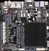
24) F_USB1/F_USB2 (USB 2.0/1.1 Headers) The headers conform to USB 2.0/1.1 specification. Each USB header can provide two USB ports via an optional USB bracket. For purchasing the optional USB bracket, please contact the local dealer. 9 1 10 2 Pin No. 1 2 3 4 5 Definition Power (5V) Power (5V) USB DXUSB DYUSB DX+ Pin No. 6 7 8 9 10 Definition USB DY+ GND GND No Pin NC •• Do not plug the IEEE 1394 bracket (2x5-pin) cable into the USB header. •• Prior to installing the USB bracket, be sure to turn off your computer and unplug the power cord from the power outlet to prevent damage to the USB bracket. 25) USB2_MPCIE_SW1/USB2_MPCIE_SW2 (Jumpers for Switching USB signals) The two headers allow for switching of USB signals. Please note that pins 1-2 or pins 2-3 of the two jumpers must be short simultaneously for activating the function. 1 USB2_MPCIE_SW1 USB2_MPCIE_SW2 1 1-2 Close: Enable USB signals to F_USB2 header. (Pins 2, 4, 6, 8, 10 enabled)(Defaults) 1 USB2_MPCIE_SW1 USB2_MPCIE_SW2 1 2-3 Close: Move USB signals to MPCIE_USB slot. 26) COMA/COMB (Serial Port Headers) Each COM header can provide one serial port via an optional COM port cable. For purchasing the optional COM port cable, please contact the local dealer. 1 9 2 10 For RS232 Devices: Pin No. Definition 1 NDCD2 NDSR3 NSIN 4 NRTS5 NSOUT 6 NCTS7 NDTR8 12V_5V 9 GND 10 NC - 18 -
-
 1
1 -
2
-
3
-
4
-
5
-
6
-
7
-
8
-
9
-
10
-
11
-
12
-
 13
13 -
 14
14 -
 15
15 -
 16
16 -
 17
17 -
 18
18 -
 19
19 -
 20
20 -
 21
21 -
 22
22 -
 23
23 -
24
-
25
-
26
-
27
-
28
-
29
-
30
-
31
-
32
-
33
-
34
 |
 |
