Gigabyte GA-P75-D3 User Manual - Page 22
CPU_FAN/SYS_FAN1/SYS_FAN2/SYS_FAN3 Fan Headers, SATA3 0 SATA 6Gb/s Connector, Controlled by Intel
 |
View all Gigabyte GA-P75-D3 manuals
Add to My Manuals
Save this manual to your list of manuals |
Page 22 highlights
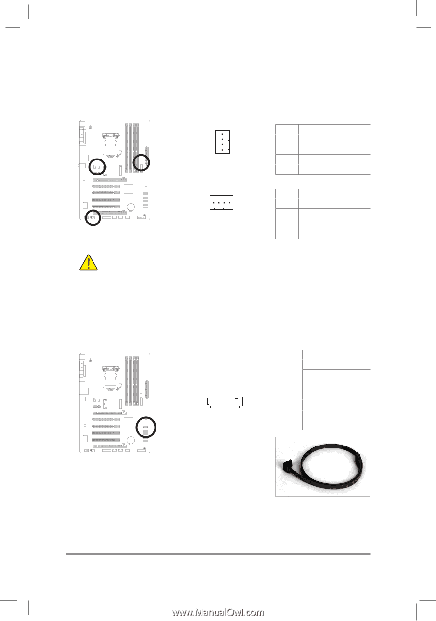
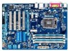
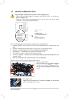
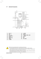
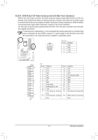
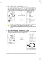
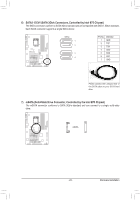
3/4) CPU_FAN/SYS_FAN1/SYS_FAN2/SYS_FAN3 (Fan Headers) All fan headers on this motherboard are 4-pin. Most fan headers possess a foolproof insertion design. When connecting a fan cable, be sure to connect it in the correct orientation (the black connector wire is the ground wire). The speed control function requires the use of a fan with fan speed control design. For optimum heat dissipation, it is recommended that a system fan be installed inside the chassis. CPU_FAN/SYS_FAN2/SYS_FAN3: Pin No. Definition 1 GND 1 CPU_FAN/SYS_FAN2/SYS_FAN3 2 +12V 3 Sense 4 Speed Control 1 SYS_FAN1 SYS_FAN1: Pin No. Definition 1 GND 2 +12V /Speed Control 3 Sense 4 VCC • Be sure to connect fan cables to the fan headers to prevent your CPU and system from overheating. Overheating may result in damage to the CPU or the system may hang. • These fan headers are not configuration jumper blocks. Do not place a jumper cap on the headers. 5) SATA3 0 (SATA 6Gb/s Connector, Controlled by Intel B75 Chipset) The SATA connector conforms to SATA 6Gb/s standard and are compatible with SATA 3Gb/s and SATA 1.5Gb/s standard. Each SATA connector supports a single SATA device. SATA3 0 1 7 Pin No. 1 2 3 4 5 6 7 Definition GND TXP TXN GND RXN RXP GND DEBUG PORT Hardware Installation - 22 - Please connect the L-shaped end of the SATA cable to your SATA hard drive.
-
 1
1 -
2
-
3
-
4
-
5
-
6
-
7
-
8
-
9
-
10
-
11
-
12
-
13
-
14
-
15
-
16
-
 17
17 -
 18
18 -
 19
19 -
 20
20 -
 21
21 -
 22
22 -
 23
23 -
 24
24 -
 25
25 -
 26
26 -
 27
27 -
28
-
29
-
30
-
31
-
32
-
33
-
34
-
35
-
36
-
37
-
38
-
39
-
40
-
41
-
42
-
43
-
44
-
45
-
46
-
47
-
48
-
49
-
50
-
51
-
52
-
53
-
54
-
55
-
56
-
57
-
58
-
59
-
60
-
61
-
62
-
63
-
64
-
65
-
66
-
67
-
68
-
69
-
70
-
71
-
72
-
73
-
74
-
75
-
76
-
77
-
78
-
79
-
80
-
81
-
82
-
83
-
84
-
85
-
86
-
87
-
88
 |
 |