Gigabyte GA-Z270X-Gaming SOC Users Manual - Page 29
CPU_OPT Water Cooling CPU Fan Header, LED_C RGB RGBW LED Strip Extension Cable Header,
 |
View all Gigabyte GA-Z270X-Gaming SOC manuals
Add to My Manuals
Save this manual to your list of manuals |
Page 29 highlights
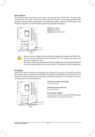
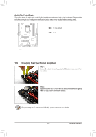
B S _S S_ _ 6) CPU_OPT (Water Cooling CPU Fan Header) B The fan header is 4-pin and possesses a foolproof insertion design. Most fan headers possess a foolproof insertion design. When connecting a fan cable, be sure to connect it in the correct orientation (the black S3 connector wire coBntSroSl desSign. is the ground wire). ThUe speed control function __ requires 3 the use of a fan with fan _spUeed _ B SF _ B_ S _S _ Pin No. Definition F_USB3 F 1 GND 1 2 Voltage Speed Control 3 Sense 4 PWM Speed Control _ _B 7) LED_C (RGB (RGBW) LED Strip Extension Cable Header) The header can be used to connect a standard 5050 RGB (RGBW) LED strip (12V/G/R/B/W), with maximum power rating of 2A (12V) and maximum length of 2m. _ 1 Pin No. 1 2 3 4 5 Definition 12V G R B W Black wire 1 12V 12V of the LED strip Connect one end of the RGB (RGBW) LED strip extension cable to the header and the other end to your RGB (RGBW) LED strip. The black wire (marked with a triangle on the plug) of the extension cable must be connected to Pin 1 (12V) of this header. The 12V pin (marked with an arrow) on the other end of the extension cable must be lined up with the 12V of the LED strip. Be careful with the connection orientation of the LED strip; incorrect connection may lead to the damage of the LED strip. B_ For how to turn on/off the lights of the RGB (RGBW) LED strip, refer to the instructions on in B_ Chapter 2, "BIUOSSB 0S_eBtup." Before installing the devices, be sure to turn off the devices and your computer. Unplug the power cord from the power outlet to prevent damage to the devices. - 29 - Hardware Installation
-
 1
1 -
2
-
3
-
4
-
5
-
6
-
7
-
8
-
9
-
10
-
11
-
12
-
13
-
14
-
15
-
16
-
17
-
18
-
19
-
20
-
21
-
22
-
23
-
 24
24 -
 25
25 -
 26
26 -
 27
27 -
 28
28 -
 29
29 -
 30
30 -
 31
31 -
 32
32 -
 33
33 -
 34
34 -
35
-
36
-
37
-
38
-
39
-
40
-
41
-
42
-
43
-
44
-
45
-
46
-
47
-
48
-
49
-
50
-
51
-
52
-
53
-
54
-
55
-
56
-
57
-
58
-
59
-
60
-
61
-
62
-
63
-
64
-
65
-
66
-
67
-
68
-
69
-
70
-
71
-
72
-
73
-
74
-
75
-
76
-
77
-
78
-
79
-
80
-
81
-
82
-
83
-
84
-
85
-
86
-
87
-
88
-
89
-
90
-
91
-
92
-
93
-
94
-
95
-
96
-
97
-
98
-
99
-
100
-
101
-
102
-
103
-
104
-
105
-
106
-
107
-
108
-
109
-
110
-
111
-
112
-
113
-
114
-
115
-
116
-
117
-
118
-
119
-
120
-
121
-
122
-
123
-
124
-
125
-
126
-
127
-
128
-
129
-
130
-
131
-
132
-
133
-
134
-
135
-
136
 |
 |
