Gigabyte GA-Z77X-UD4H Manual - Page 23
Onboard Buttons, Switches and LEDs, BIOS Switch and BIOS LED Indicators - overclock
 |
View all Gigabyte GA-Z77X-UD4H manuals
Add to My Manuals
Save this manual to your list of manuals |
Page 23 highlights
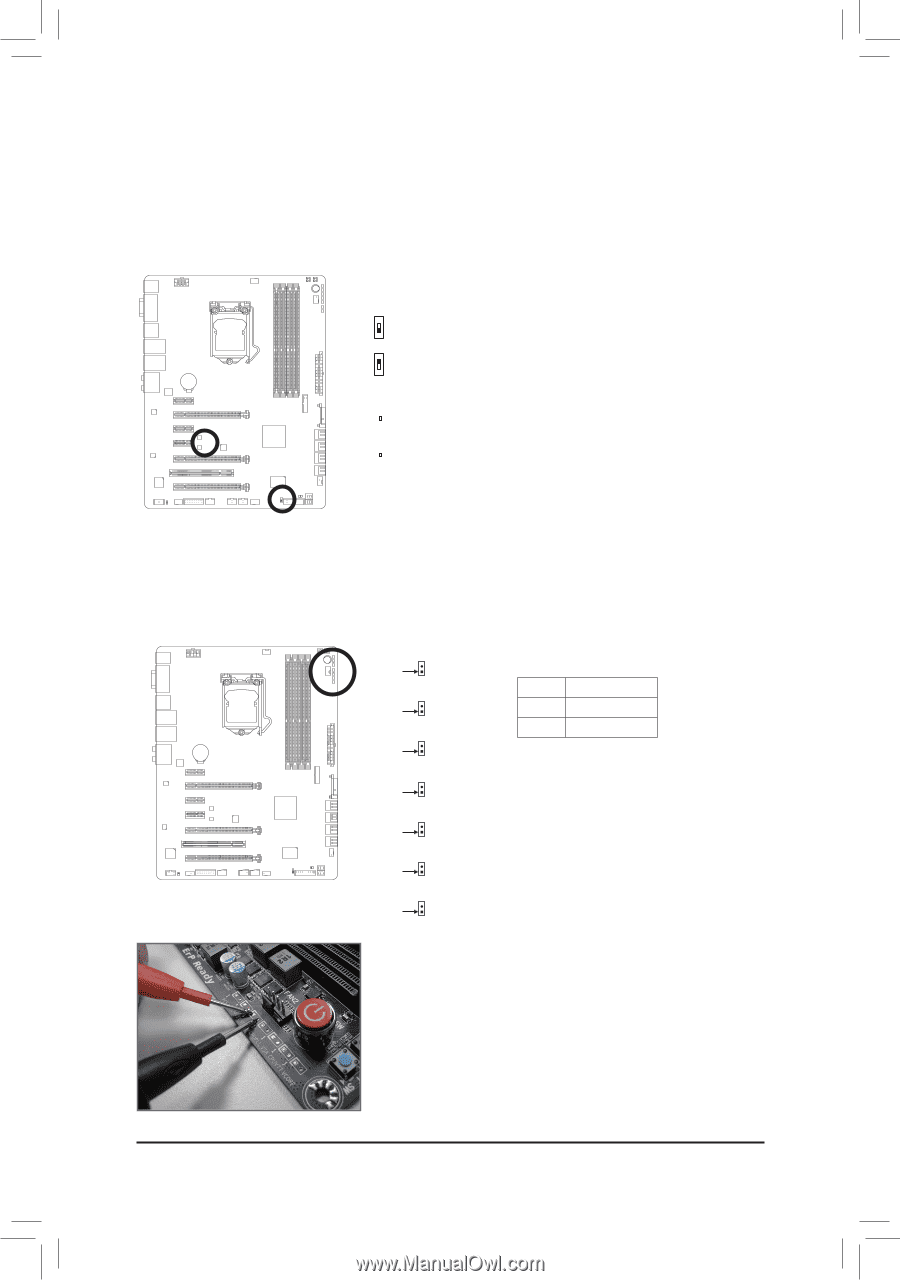
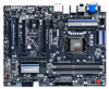
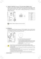
1-8 Onboard Buttons, Switches and LEDs F_USB30 F_AUDIO(H) F_PANEL(NH) BIOS Switch and BIOS LED InFd_UiScBa30tors F_AUDIO(H) F_PANEL(NH) The BIOS switch (SW4) allows users to easily select a different BIOS for boot up or overclocking, helping to reduce BIOS failure during overclocking. ThFe_ULSBE30D indicator (MBIOS_LED/BBIFO_ASUD_IOL(HE) D) shows which BIOS is active. F_PANEL(NH) F_UBSIBO30S Switch: SW4 F_AUDIO(H) F_USB30 1: Main BIOS (Boot from tDFh_BeA_UPmDOIROaT(iHn) BIOS) 1 F_PANEL(NH) BIOS Switcher (X58A-OC) F_PANEL(NH) 1 TPM DIP w/housing 1 23 DIP 1 23 DIP 1 1 23 DIP 1 1 23 DIP 1 1 23 DIP 1 1 23 DIP 1 1 23 1 1 F_USB30 2: Backup BIOS (Boot fromDF_BA_tUhPDOeIRObT(Ha)ckup BIOS) 1 1 BIOS Switcher (X58A-OC) M_SATA F_PANEL(NH) 1 Voltage measurement points(G1.Sniper 3) BIOS Switcher (SW4) TFP_MUBSBI3O0S LED Indicators: VoltDagBe_PmOeRasTurement module(X58A-OC) F_AUDIO(H) w/housing BBIOS_LED (The backup BIOS is active) 1 1 BIOS Switcher (X58A-OC) M_SATA F_PANEL(NH) PWM1 Switch (X58A-OC) 1 23 DIP TPM w/housing VoltDagBe_PmOeRasTurement module(X58A-OC) MBIOS_LED (The main BIOS is active) 1 1 BIOS Switcher (X58A-OC) M_SATA PWM1 SDwIPitch (X58A-OC) DIP 1 23 1 23 DIP TPM w/housing VoltDagBe_PmOeRasTurement module(X58A-OC) PCIe power connector (SATA)(X58A-OC) 1 BIOS S1w2it3cher (X58A-OC) PWM1 SDwIPitch (X58A-OC) 1 M_SATA DIP 1 23 1 23 DIP TPM w/housing VoltDagBe_PmOeRasTurement module(X58A-OC) PCIe power connector (SATA)(X58A-OC) 1 BIOS S1w2it3cher (X58A-OC) PWM1 SDwIPitch (X58A-OC) 1 M_SATA DIP 1 23 1 23 DIP Voltage Measurement Points TPM w/housing VoltDagBe_PmOeRasTurement module(X58A-OC) PCIe power connector (SATA)(X58A-OC) 1 BIOS S1w2it3cher (X58A-OC) PWM1 SDwIPitch (X58A-OC) 1 M_SATA 1 23 DIP DDIIPP 11 22 33 PCIe power connector (SATA)(X58A-OC) DIP 1 23 1 Users can use a multimeter to measure component voltages, incluVodltaingegmeVasCureOmeRnt Emo,duCle(PX5U8AV-OCT)T, VSA, 1C2 3PUPLL, M_SATA VDIMM, DDRVTT, and PCHIO. YouTwcP/hMaounsineg mploy following way to measPuCrIee pocwoermcopnnoecntoer (nSAtTAv)o(Xl5t8aA-gOeC)s. PWM SDwIPitch (X58A-OC) DIP 1 23 1 23 DIP PWM Switch (X58A-OC) 1 23 DDIIPP TPM w/housing Voltage measurement points(G1.SniperV3o)ltage measuremBeIOnSt mSowdituclhee(Xr5(S8AW-4O)C) VCORE PCIe power connector (SATA)(X58A-OC) PWM SDwIPitch (X58A-OC) DIP 1 23 1 23 11 22 33 Pin 1 DIP 1 23 Voltage measurement CPUVTT points(G1.SnipePr 3i)n PNCIoe.poweDr cBeoInfOinnSeciSttoiworit(ncShAeTrA(S)(WX548)A-OC) DIP Voltage measurement module(X58A-OC) DIP 1 23 Pin 1 1 Power 1 23 2 GND Voltage measurement points(G1.Sniper 3) BIOS Switcher (SW4) VSA PCIe power connector (SATA)(X58A-OC) DIDIPP 11 2233 11 DDIPIP 11 2233 11 Pin 1 Voltage measurement points(G1.Sniper 3) BIOS Switcher (SW4) 11 CPUPLL DB_PORT Pin 1 Voltage measurement points(G1.Sniper 3) VDIMM BIOS Switcher (SW4) Pin 1 Voltage measurement points(G1.Sniper 3) DDRVTT BIOS Switcher (SW4) Pin 1 Voltage measurement points(G1.Sniper 3) PCHIO BIOS Switcher (SW4) Pin 1 Steps: Connect the red lead of the multimeter to the pin 1 (Power) of a voltage measurement point and the black lead to the pin 2 (ground). BIOS Switcher (X58A-OC) 11 M_SATA F_USB30 F_AUDIO(H) F_PANEL(NH) - 23 - Hardware Installation
-
 1
1 -
2
-
3
-
4
-
5
-
6
-
7
-
8
-
9
-
10
-
11
-
12
-
13
-
14
-
15
-
16
-
17
-
 18
18 -
 19
19 -
 20
20 -
 21
21 -
 22
22 -
 23
23 -
 24
24 -
 25
25 -
 26
26 -
 27
27 -
 28
28 -
29
-
30
-
31
-
32
-
33
-
34
-
35
-
36
-
37
-
38
-
39
-
40
-
41
-
42
-
43
-
44
-
45
-
46
-
47
-
48
-
49
-
50
-
51
-
52
-
53
-
54
-
55
-
56
-
57
-
58
-
59
-
60
-
61
-
62
-
63
-
64
-
65
-
66
-
67
-
68
-
69
-
70
-
71
-
72
-
73
-
74
-
75
-
76
-
77
-
78
-
79
-
80
-
81
-
82
-
83
-
84
-
85
-
86
-
87
-
88
-
89
-
90
-
91
-
92
-
93
-
94
-
95
-
96
-
97
-
98
-
99
-
100
-
101
-
102
-
103
-
104
-
105
-
106
-
107
-
108
-
109
-
110
-
111
-
112
-
113
-
114
-
115
-
116
-
117
-
118
-
119
-
120
 |
 |