Gigabyte GS-R12P4E Manual
Gigabyte GS-R12P4E Manual
 |
View all Gigabyte GS-R12P4E manuals
Add to My Manuals
Save this manual to your list of manuals |
Gigabyte GS-R12P4E manual content summary:
- Gigabyte GS-R12P4E | Manual - Page 1
GS-R12P4E GS-R12P8E GS-R12P4F GS-R12P8F LGA1356 socket motherboard for Intel® Xeon® series processors Service Guide Rev. 1.0 - Gigabyte GS-R12P4E | Manual - Page 2
respective owners. Disclaimer Information in this manual is protected by copyright laws and is the property of GIGABYTE. Changes to the specifications and features in this manual may be made by GIGABYTE without prior notice. No part of this manual may be reproduced, copied, translated, transmitted - Gigabyte GS-R12P4E | Manual - Page 3
Before using this information and the product it supports, please read the following general information. 1. This Service Guide provides you with all technical information relating to the BASIC CON- FIGURATION decided for GIGABYTE's "global" product offering. To better fit local marketrequirements - Gigabyte GS-R12P4E | Manual - Page 4
17 2-4-2 Installing a Memory 19 2-5 Installing the PCI Expansion Card 20 2-6 Installing the Hard Disk Drive 21 2-6-1 GS-R12P4E/GS-R12P4F Hard Disk Drive Installation 21 2-6-1 GS-R12P8E/GS-R12P8F Hard Disk Drive Installation 22 2-7 Removing and Installing the Fan Duct 23 2-8 Replacing the FAN - Gigabyte GS-R12P4E | Manual - Page 5
5-6 Boot Option Menu 71 5-7 Boot Manager 72 5-8 Exit Menu...73 5-9 BIOS Beep Codes 75 5-9-1 PEI Beep Codes...75 5-9-2 DXE Beep Codes...75 5-10 BIOS Recovery Instruction 76 - 5 - - Gigabyte GS-R12P4E | Manual - Page 6
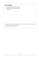
Box Contents GS-R12P4E/GS-R12P8E (PSU 500W) GS-R12P4F/GS-R12P8F (PSU 400W) Driver CD • The box contents above are for reference only and the actual items shall depend on the product package you obtain. - Gigabyte GS-R12P4E | Manual - Page 7
safely when it is used in accordance with its marked electricalratings and product usage instructions • Do not use this product near water or a heat source.* Set specified in the product's documentation. • Only authorized service technicians should repair laser devices. Precaution for Product with - Gigabyte GS-R12P4E | Manual - Page 8
environment. This equipmentgenerates, uses, and can radiate radio frequency energy and, if not installed and used in accordance withthe instruction manual, may cause harmful interference to radio communications. Operation of thisequipment in a residential area is likely to cause harmful interference - Gigabyte GS-R12P4E | Manual - Page 9
please contact your local government office, your household waste disposal service or where you purchased the product for details of environmentally may contact us at the Customer Care number listed in your product's user's manual and we will be glad to help you with your effort. Battery Warning: - Gigabyte GS-R12P4E | Manual - Page 10
of electrostatic discharge (ESD). Prior to installation, carefully read the service guide and follow these procedures: • Prior to installation, do not remove are uncertain about any installation steps or have a problem related to the use of the product, please consult a certified computer technician. - Gigabyte GS-R12P4E | Manual - Page 11
1-2 Product Specifications CPU Chipset Memory LAN Expansion Slot Onboard Graphics Mass Storage (GS-R12P4E) (GS-R12P4F) Mass Storage (GS-R12P8E) (GS-R12P8F) System Fans USB ŠŠ Support for Dual Intel® Xeon® Sandy-bridge-EN processors in 1356 socket ŠŠ Intel® Xeon® Quad/Eight Core in LGA 1356 socket - Gigabyte GS-R12P4E | Manual - Page 12
(mm) Dimension Electrical ŠŠ Fixed 1U PSU 500W 100-240VAC at 80 plus gold level (GS-R12P4E/GS-R12P8E) Power Supply ŠŠ Fixed 1U PSU 400W 100-240VAC at 80 plus gold level (GS-R12P4F/GS-R12P8F) * GIGABYTE reserves the right to make any changes to the product specifications and product-related - Gigabyte GS-R12P4E | Manual - Page 13
Chapter 2 System Hardware Installation Pre-installation Instructions Perform the steps below before you open the server or before you remove or replaceany component. • Back up all important system and data files before - Gigabyte GS-R12P4E | Manual - Page 14
Cover Before you remove or install the system cover • Make sure the system is not turned on or connected to AC power. Follow these instructions to remove the system cover: 1. Loosen and remove the thumbscrew securing the front chassis cover. 2. Slide the cover horizontally to the back and remove - Gigabyte GS-R12P4E | Manual - Page 15
you begin to install the CPU: • Make sure that the motherboard supports the CPU. • Always turn off the computer and unplug the power cord described in the following sections unless you are a qualified service technician. Follow these instructions to install the CPU: 1. Raise the metal locking lever - Gigabyte GS-R12P4E | Manual - Page 16
2-3 Installing the Heat Sink Follow these instructions to install the heat sinks: 1. Apply thermal compound evenly on the top of the CPU. 2. Remove the protective cover from the underside of the heat - Gigabyte GS-R12P4E | Manual - Page 17
to insert the memory, switch the direction. 2-4-1 Three Channel Memory Configuration The system provides 12 DDR3 memory sockets for per CPU and supports Three Channel Technology. After the memory is installed, the BIOS will automatically detect the specifications and capacity of the memory. Enabling - Gigabyte GS-R12P4E | Manual - Page 18
Due to CPU limitation, read the following guidelines before installing the memory in Dual or 3 Channel mode. Dual Channel-1. Dual Channel mode cannot be enabled if only one DDR3 memory module is installed. 2. When enabling Dual Channel mode with two or four modules, it is recommended that memory of - Gigabyte GS-R12P4E | Manual - Page 19
the power cord from the power outlet to prevent damage to the memory module. Be sure to install DDR3 DIMMs on this motherboard. Follow these instructions to install the Memory: 1. Insert the DIMM memory module vertically into the DIMM slot, and push it down. 2. Close the plastic clip at both edges - Gigabyte GS-R12P4E | Manual - Page 20
To install a PCI card, a riser card must be installed. Follow these instructions to PCI Expansion card: 1. Loosen the riser bracket screw. 2. lift the mini PCI card with three screws. 6. Orient the PCI card with the riser guide connector and push into the slot until the PCI card sits in the PCI card - Gigabyte GS-R12P4E | Manual - Page 21
the bay if inserted incorrectly. • Make sure that the HDD is connected to the HDD connector on the backplane. 2-6-1 GS-R12P4E/GS-R12P4F Hard Disk Drive Installation Follow these instructions to install the Hard disk drive: 1. Press the release button. 2. Pull the locking lever to remove the HDD tray - Gigabyte GS-R12P4E | Manual - Page 22
2-6-1 GS-R12P8E/GS-R12P8F Hard Disk Drive Installation Follow these instructions to install the Hard disk drive: 1. Press the release button. 2. Pull the locking lever to remove the HDD tray. 3. Slide hard disk into blank. 4. Secure - Gigabyte GS-R12P4E | Manual - Page 23
2-7 Removing and Installing the Fan Duct Follow these instructions to remove/install the fan duct: 1. Lift up to remove the fan duct 2. To install the fan duct, align the fan duct with the guiding groove. Push down the fan duct into chassis until its firmly seats - 23 - Hardware Installation - Gigabyte GS-R12P4E | Manual - Page 24
2-8 Replacing the FAN Assemblly Follow these instructions to replace the fan assembly: 1. Lift up the fan assembly from the chassis. 2. Reverse the previous step to install the replacement fan assembly. Hardware Installation - 24 - - Gigabyte GS-R12P4E | Manual - Page 25
2-10 Replacing the Power Supply Follow these instructions to replace the power supply: 1. Disconnect the three power cables. 2. Remove the four screws securing on the power supply. 3. Lift the power supply out of - Gigabyte GS-R12P4E | Manual - Page 26
Chapter 3 System Appearance 3-1 Front View GS-R12P4E/GS-R12P4F 32 1 No. Decription 1. HDD bays 2. Front Panel LEDs and buttons 3. Front USB 2.0 ports GS-R12P8E/GS-R12P8F 32 1 No. Decription 1. HDD bays 2. Front Panel LEDs and buttons 3. Front USB 2.0 ports Hardware Installation - 26 - - Gigabyte GS-R12P4E | Manual - Page 27
3-2 Rear View 1 2 3 4 5 67 8 No. Decription 1. Power cord 2. VGA port 3. Serial port 4. USB 2.0 ports 5. RJ-45 LAN ports 6. Server management LAN port 7. ID switch button 8. Low-profile riser card bay - 27 - Hardware Installation - Gigabyte GS-R12P4E | Manual - Page 28
3-3 Front Panel LED and Buttons 1 2 3 5 7 9 10 No. Name 1 HDD Status LED 2 Power LED Color Green Amber Green/ Amber N/A Green Green N/A LAN1 LED 3 LED LAN2 LED 4 LED 5 ID LED Green Green N/A Green Green N/A Blue N/A Status On Blink On 46 HDD locate HDD access HDD fault 8 Description Blink - Gigabyte GS-R12P4E | Manual - Page 29
System 6 Status LED Amber N/A 7 Reset button 8 NMI button 9 ID button 10 Power button Critical condition. May indicate the following: • Power module failure • System fan failure • Power supply voltage issue • System temperature/voltage issue On Non-critical condition. May indicate the following: - Gigabyte GS-R12P4E | Manual - Page 30
3-4 Rear System LAN LEDs 1 21 2 34 No. Name 1 Connection/ Speed LED 2. Activity LED 3. Connection/ Speed LED 4. Activity LED Color Yellow Green N/A Green Green N/A Green Green N/A Green Green N/A Status On Blink On Blink Off Blink On Off On Blink Off Blink On Off Description Linking at 1 - Gigabyte GS-R12P4E | Manual - Page 31
3-5 Hard Disk Drive LEDs No Description 1 HDD Access HDD Locate HDD Failure HDD connected and rebuilding data 2 Reserve 1 2 Multi Color LEDs LED Active LED Active Green Amber Blink Off On Off Off On Blink Blink (Alternative) - 31 - Hardware Installation - Gigabyte GS-R12P4E | Manual - Page 32
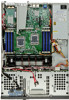
Chapter 4 Motherboard Components 4-1 GA-7PESE3 Motherboard Components 41 43 45 1 38 39 40 42 44 46 2 3 4 5 6 37 7 36 47 35 48 34 49 33 322 29 28 27 26 25 31 24 8 9 10 11 12 13 14 15 16 17 18 30 23 22 21 20 19 Hardware Installation - 32 - - Gigabyte GS-R12P4E | Manual - Page 33
1 slot 1 (for primary CPU) Channel 1 slot 0 (for primary CPU) HDD back plane connector Front panel connector SATA port1 DOM support jumper SATA port0 DOM support jumper SATA 6Gb/s connectors SATA 3Gb/s connectors Front USB connector Serial port connector Mini SAS connector (SATA signal) Mini SAS - Gigabyte GS-R12P4E | Manual - Page 34
46 SSB_ME1 47 BAT 48 BMC_FRB3 49 BIOS_WP ME enable/disable jumper CMOS battery Force to Stop FRB3 Timer Jumper BIOS write protect jumper Hardware Installation - 34 - - Gigabyte GS-R12P4E | Manual - Page 35
4-2 Jumper Setting 14 62 5 9 3 7 8 No. Jumper Code Jumper Setting 1. CLR_CMOS1 1-2 Close: Normal operation (Default setting) (Clearing CMOS Jumper) 2-3 Close: Clear CMOS data 2. BIOS_RVCR1 1-2 Close: Normal operation (Default setting) (BIOS Recovery Jumper) 2-3 Close: BIOS recovery - Gigabyte GS-R12P4E | Manual - Page 36
No. Jumper Code SSB_ME1 5. (ME enable/ disable Jumper) SSB_ME2 6. (ME enable/ disable Jumper) SATA_DOM0 7. (SATA port 0 DOM Jumper) SATA_DOM1 8. (SATA port 1 DOM Jumper) BMC_FRB3 9. (Force to Stop FRB3 Timer Jumper) Jumper Setting 1-2 Close: Normal operation. (Default setting) 2-3 - Gigabyte GS-R12P4E | Manual - Page 37
4-3 Back Plane Boad (GC-BS14U2/for GS-R12P4E/GS-R12P4F) 13 24 5 79 6 8 10 14 15 11 13 16 12 23 22 21 20 19 18 17 Item 1 FAN1 2 FAN2 3 FAN3 4 FAN4 5 FAN5 6 FAN6 7 - Gigabyte GS-R12P4E | Manual - Page 38
(GC-BS16U2/for GS-R12P8E/GS-R12P8F) 14 9 13 13 24 5 6 7 8 10 11 12 15 16 17 28 27 Item 1 FAN1 2 FAN2 3 FAN3 4 FAN4 5 FAN5 6 FAN6 7 FAN7 8 FAN8 9 FAN9 10 FAN10 - Gigabyte GS-R12P4E | Manual - Page 39
J2/J3 Jumper Setting LSI, SCU SATA J2 2-3 Close 2-3 Close J3 2-3 Close 1-2 Close - 39 - Hardware Installation - Gigabyte GS-R12P4E | Manual - Page 40
Setup program, press the key during the POST when the power is turned on. • BIOS flashing is potentially risky, if you do not encounter problems of using the current BIOS version, it is recommended that you don't flash the BIOS. To flash the BIOS, do it with caution. Inadequate BIOS - Gigabyte GS-R12P4E | Manual - Page 41
Main This setup page includes all the items in standard compatible BIOS. Advanced This setup page includes all the items of AMI BIOS special enhanced features. (ex: Auto detect fan and temperature status, automatically configure hard disk parameters.) Chipset This setup page includes all the - Gigabyte GS-R12P4E | Manual - Page 42
5-1 The Main Menu Once you enter the BIOS Setup program, the Main Menu (as shown below) appears on the screen. Use arrow keys to move among the items and press to accept or enter other sub-menu. Main Menu Help The on-screen description of a highlighted setup option is displayed on the bottom - Gigabyte GS-R12P4E | Manual - Page 43
BIOS Information BIOS Version Display version number of the BIOS setup utility. Memory Information Total Memory Determines how much total memory is present during the POST. System Date Set the date following the weekday-month-day- year format. System Time Set the system time following the hour- - Gigabyte GS-R12P4E | Manual - Page 44
5-2 Advanced Menu The Advanced menu display submenu options for configuring the function of various hardware components. Select a submenu item, then press Enter to access the related submenu screen. - 44 - BIOS Setup - Gigabyte GS-R12P4E | Manual - Page 45
5-2-1 PCI Configuration PCI Express Slot #1/2/3/4 Option ROM When enabled, This setting will initialize the device expansion ROM for the related PCI-E slot. Options available: Enabled/Disabled. Default setting is Enabled. Onboard LAN1/2 Controller Enable/Disable Onboard LAN controller . Options - Gigabyte GS-R12P4E | Manual - Page 46
Select Enabled to activate TPM support feature. Options available: Enabled/Disabled. Default setting is Enabled. TPM State Select Enabled to activate TPM State function. Options available: Enabled/Disabled. Default setting is - Gigabyte GS-R12P4E | Manual - Page 47
5-2-3 CPU Configuration BIOS Setup - 47 - - Gigabyte GS-R12P4E | Manual - Page 48
the information of the processor core. Intel HT Technology Display Intel Hyper Threading Technology function support information. Intel VT-x Technology Display Intel Virtualization Technology function support information. Cache Information L1 Data Cache Display the information of L1 Data Cache. L1 - Gigabyte GS-R12P4E | Manual - Page 49
Display the information of total L3 Cache per socket. CPU Speed Display the current installed CPU speed. 64-bit Display the supported infprmation of installed CPU. Hyper-threading The Intel Hyper Threading Technology allows a single processor to execute two or more separate threads concurrently - Gigabyte GS-R12P4E | Manual - Page 50
limit. Options available: C0/C1/C6/C7/No Limit. Default setting is No Limit. (Note) This item is present only if you install a CPU that supports this feature. For more information about Intel CPUs' unique features, please visit Intel's website. - 50 - BIOS Setup - Gigabyte GS-R12P4E | Manual - Page 51
5-2-4 Runtime Error Logging Runtime Error Logging Support Enable/Disable Runtime error logging support. Options available: Enabled/Disabled. Default setting is Disabled. BIOS Setup - 51 - - Gigabyte GS-R12P4E | Manual - Page 52
5-2-5 SATA Configuration SATA Port 0/1/2/3/4/5 (Note) Press [Enter] to view the installed HDD devices. SATA Mode Select the on chip SATA type. IDE Mode: When set to IDE, the SATA controller disables its RAID and AHCI functions and runs in the IDE emulation mode. This is not allowed to access RAID - Gigabyte GS-R12P4E | Manual - Page 53
5-2-6 SAS Configuration Device 0/1/2/3 (Note) Press [Enter] to view the installed HDD devices. (Note) The number of SATA and SAS devices depends of the PCH SKU. BIOS Setup - 53 - - Gigabyte GS-R12P4E | Manual - Page 54
5-2-7 Super IO Configuration - 54 - BIOS Setup - Gigabyte GS-R12P4E | Manual - Page 55
Super IO Chip Display the model name of super IO chipset. Serial Port 1/2 Configuration(Note) When enabled allows you to configure the serial port settings. When set to Disabled, displays no configuration for the serial port. Options available: Enabled/Disabled. Default setting is Enabled. Device - Gigabyte GS-R12P4E | Manual - Page 56
5-2-8 Serial Port Console Redirection - 56 - BIOS Setup - Gigabyte GS-R12P4E | Manual - Page 57
Options available: Enabled/Disabled. Default setting is Disabled. Console Redirection Settings Out-of-Bnad Mgmt Port Microsoft Windows Emerency Management Service (EMS) allows for remote management of a Windows Server OS through a serial port. Options available: COM1 Terminal Type Select a terminal - Gigabyte GS-R12P4E | Manual - Page 58
5-2-9 Network Stack Network Stack Enable/Disable the network stack (PXE and UEFI) Options available: Enabled/Disabled. Default setting is Disabled. - 58 - BIOS Setup - Gigabyte GS-R12P4E | Manual - Page 59
5-3 Chipset Menu The Chipset menu display submenu options for configuring the function of North Bridge and South Bridge. Select a submenu item, then press Enter to access the related submenu screen. BIOS Setup - 59 - - Gigabyte GS-R12P4E | Manual - Page 60
5-3-1 North Bridge Configuration Compatibility RID Enable/Disable Compatibility RID function. Options available: Enabled/Disabled. Default setting is Enabled. Memory Configuration Total Memory Determines how much total memory is present during the POST. Current Memory Mode Displays the cuurent - Gigabyte GS-R12P4E | Manual - Page 61
Numa Enable/Disable Non Uniform Memory Access (NUMA) function. Options available: Enabled/Disabled. Default setting is Enabled. Thermal Throtting Options available: CLTT/OLTT. Default setting is CLTT. DIMM Voltage Configure the DIMM voltage. Options available: Auto/ Force 1.5v/Force 1.35v. Default - Gigabyte GS-R12P4E | Manual - Page 62
5-3-1-1 IOH Configuration - 62 - BIOS Setup - Gigabyte GS-R12P4E | Manual - Page 63
Define the display device priority. Options available: Onboard/Offboard. Default setting is Offboard. Gen3 Equalization WA's Enable/DIsable the support for Gen3 Equalization Workaround. Options available: Enabled/Disabled. Default setting is Disabled. PCIE Slot1 Speed Select PCIe slot 1 speed - Gigabyte GS-R12P4E | Manual - Page 64
5-3-1-2 DIMM Information DIMM Information: DIMM Group: CPU Socket 0 DIMM Information CPU Socket 0: DDR3_P0_A0/DDR3_P0_A1/DDR3_P0_B0/DDR3_P0_B1/ DDR3_P0_C0/DDR3_P0_C1 Status CPU Socket 1: DDR3_P0_D0/DDR3_P0_D1/DDR3_P0_E0/DDR3_P0_E1/ DDR3_P0_F0/DDR3_P0_F1 Status The size of memory installed on each - Gigabyte GS-R12P4E | Manual - Page 65
Displays the name and stepping information of the south bridge. SB Chipset Configuration PCH Compatibility RID Enable/Disable PCH Compatibility RID support. Options available: Enabled/Disabled. Default setting is Disabled. Restore on AC Power Loss (Note) Defines the power state to resume to - Gigabyte GS-R12P4E | Manual - Page 66
5-3-3 ME Subsystem Intel ME Subsystem Configuration Enable/Disable ME subsystem configuration. Options available: Enabled/Disabled. Default setting is Enabled. - 66 - BIOS Setup - Gigabyte GS-R12P4E | Manual - Page 67
5-4 Security Menu The Security menu allows you to safeguard and protect the system from unauthorized use by setting up access passwords. There are two types of passwords that you can set: • Administrator Password Entering this password will allow the user to access and change all settings in the - Gigabyte GS-R12P4E | Manual - Page 68
5-5 Server Management Menu System Information Displays basic system ID information, as well as BIOS version. Press Enter to access the related submenu. BMC LAN Configuration BMC LAN Configuration. Press Enter to access the related submenu. Select NCSI and Dedicated LAN Switch NCSI and dedicated - Gigabyte GS-R12P4E | Manual - Page 69
5-5-1 System Information The System Management submenu is a simple display page for basic system ID and BMC information. Items on this window are non-configurable. BIOS Setup - 69 - - Gigabyte GS-R12P4E | Manual - Page 70
5-5-2 BMC LAN Configuration Configuration Source Select to configure LAN channel parameters statically or dynamically (DHCP). Do nothing option willnot modify any BMC network parameters during BIOS phase. Options available: Static/Dynamic/Do Nothing. IP Address Display IP Address information. - Gigabyte GS-R12P4E | Manual - Page 71
5-6 Boot Option Menu The Boot menu allows you to set the drive priority during system boot-up. BIOS setup will display an error message if the legacy drive(s) specified is not bootable. By default, the server searches for boot devices in the following secquence: 1. UEFI device. 2. Hard drive. - Gigabyte GS-R12P4E | Manual - Page 72
5-7 Boot Manager The Boot manager menu allows you to specify the boot-up drive. BIOS setup will display an error message if the legacy drive(s) specified is not bootable. UEFI: Built-in EFI Shell Press Enter to configure the device as the boot-up drive. - 72 - BIOS Setup - Gigabyte GS-R12P4E | Manual - Page 73
5-8 Exit Menu The Exit menu displays the various options to quit from the BIOS setup. Highlight any of the exit options then press Enter. Save Changes and Exit Saves changes made and close the BIOS setup. Options available: Yes/No. Discard Changes and Exit Discards changes made and close the BIOS - Gigabyte GS-R12P4E | Manual - Page 74
Save as User Default Values Saves as user default and close the BIOS setup. Options available: Yes/No. Load User Default Values Loads the user default settings for all BIOS setup parameters. Options available: Yes/No. - 74 - BIOS Error Code - Gigabyte GS-R12P4E | Manual - Page 75
5-9 BIOS Beep Codes 5-9-1 PEI Beep Codes # of Beeps 1 1 2 3 3 4 4 7 Description Memory not Installed. Memory was installed twice (InstallPeiMemory routine in PEI Core called twice) Recovery started DXEIPL was not found DXE Core Firmware Volume was not found Recovery failed S3 Resume failed Reset - Gigabyte GS-R12P4E | Manual - Page 76
becomes corrupt the boot block can be used to restore the BIOS to a working state. To restore your BIOS, please follow the instructions listed below: Recovery Instruction: 1. Change xxx.ROM to amiboot.rom. 2. Copy amiboot.rom and AFUDOS.exe to USB diskette. 3. Setting BIOS Recovery jump to enabled - Gigabyte GS-R12P4E | Manual - Page 77
6. BIOS update. BIOS Error Code - 77 -
-
 1
1 -
 2
2 -
 3
3 -
 4
4 -
 5
5 -
 6
6 -
 7
7 -
8
-
9
-
10
-
11
-
12
-
13
-
14
-
15
-
16
-
17
-
18
-
19
-
20
-
21
-
22
-
23
-
24
-
25
-
26
-
27
-
28
-
29
-
30
-
31
-
32
-
33
-
34
-
35
-
36
-
37
-
38
-
39
-
40
-
41
-
42
-
43
-
44
-
45
-
46
-
47
-
48
-
49
-
50
-
51
-
52
-
53
-
54
-
55
-
56
-
57
-
58
-
59
-
60
-
61
-
62
-
63
-
64
-
65
-
66
-
67
-
68
-
69
-
70
-
71
-
72
-
73
-
74
-
75
-
76
-
77
 |
 |

GS-R12P4E
GS-R12P8E
GS-R12P4F
GS-R12P8F
LGA1356 socket motherboard for Intel
®
Xeon
®
series processors
Service Guide
Rev. 1.0