Gigabyte GV-NX71G512P8 Manual - Page 8
Hardware Installation
 |
View all Gigabyte GV-NX71G512P8 manuals
Add to My Manuals
Save this manual to your list of manuals |
Page 8 highlights
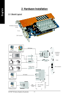
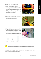
English 2. Hardware Installation 2.1. Board Layout VGA Monitor Connector (15-pin) TV-out DVI-I Connector OR Analog LCD Monitor Analog Monitor HDTV OR NTSC / PAL TV Projector OR NTSC / PAL TV Projector VGA Output Y Pr Pb/AV Output S-Video Output DVI Output Digital LCD Monitor Analog LCD Monitor VGA Output DVI-I to D-Sub Adapter GV-NX71G Series Graphics Accelerator - 4 - VGA Monitor Connector (15-pin) TV-Out DVI-I Connector
-
 1
1 -
2
-
 3
3 -
 4
4 -
 5
5 -
 6
6 -
 7
7 -
 8
8 -
 9
9 -
 10
10 -
 11
11 -
 12
12 -
 13
13 -
14
-
15
-
16
-
17
-
18
-
19
-
20
-
21
-
22
-
23
-
24
-
25
-
26
-
27
-
28
-
29
-
30
-
31
-
32
-
33
-
34
-
35
-
36
-
37
-
38
-
39
-
40
-
41
-
42
 |
 |

GV-NX71G Series Graphics Accelerator
- 4 -
English
2. Hardware Installation
TV-out
VGA Monitor Connector
(15-pin)
DVI-I Connector
2.1. Board Layout
TV-Out
VGA Monitor
Connector
(15-pin)
DVI-I Connector
S-Video Output
Pb/AV Output
Pr
Y
VGA Output
DVI-I to D-Sub
Adapter
Analog LCD Monitor
Analog Monitor
OR
Digital LCD Monitor
DVI Output
NTSC / PAL TV
Projector
HDTV
VGA
Output
OR
NTSC / PAL TV
Projector
OR
Analog LCD Monitor