Gigabyte GV-R455D3-512I Manual - Page 5
Hardware Installation - gv -
 |
UPC - 818313006578
View all Gigabyte GV-R455D3-512I manuals
Add to My Manuals
Save this manual to your list of manuals |
Page 5 highlights
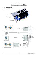
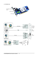
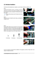
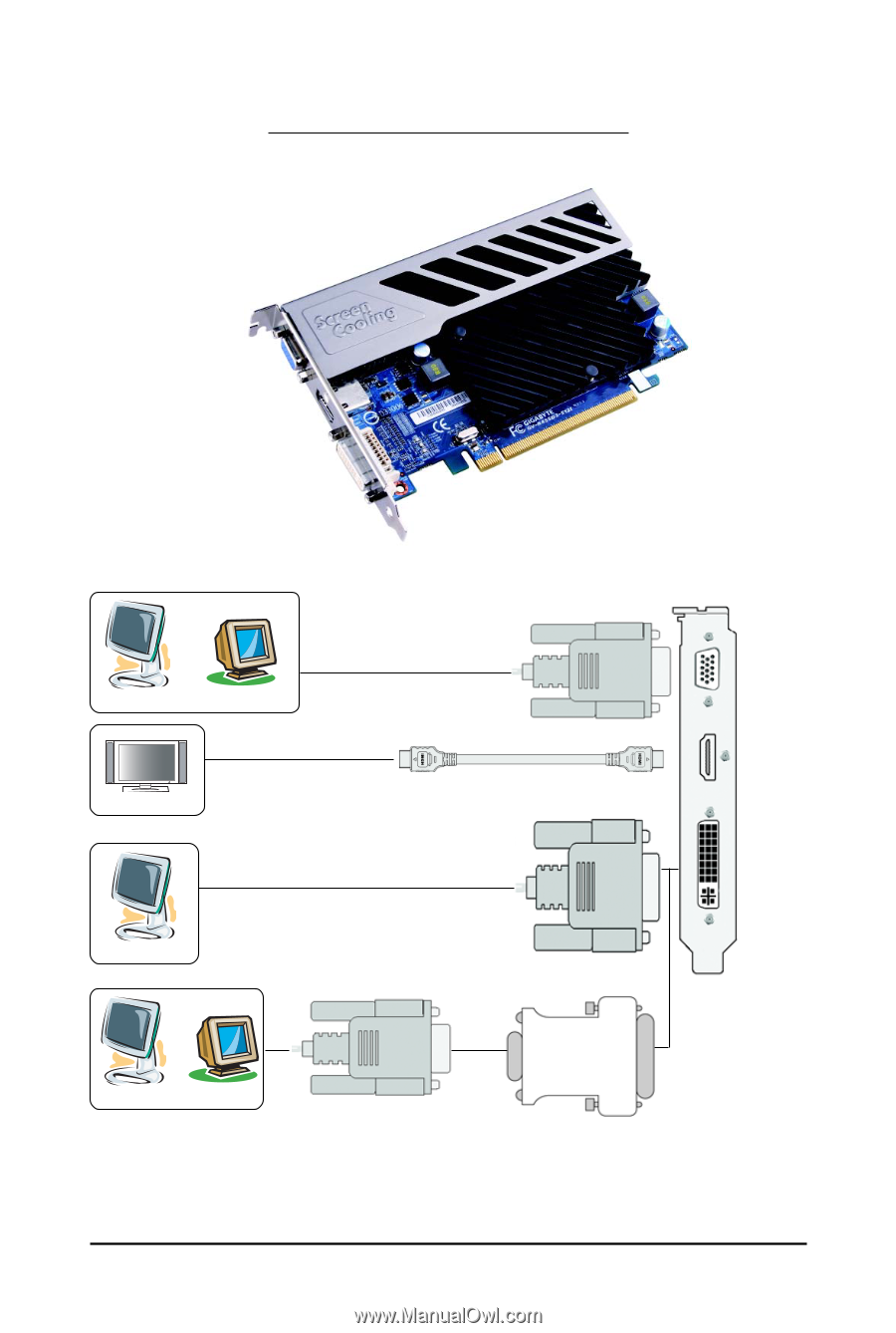
2. Hardware Installation 2.1. Board Layout 1. GV-R455D3-512I D-Sub Monitor Connector (15-pin) HDMI Connector DVI-I Connector or Analog LCD Monitor Analog CRT Monitor D-Sub Output HDMI TV Digital LCD Monitor DVI Output or Analog LCD Monitor Analog Monitor D-Sub Output DVI-I to D-Sub Adapter D-Sub Monitor Connector (15-pin) HDMI Connector DVI-I Connector - 5 - Hardware Installation
-
 1
1 -
 2
2 -
 3
3 -
 4
4 -
 5
5 -
 6
6 -
 7
7 -
 8
8 -
 9
9 -
 10
10 -
 11
11 -
12
-
13
-
14
-
15
-
16
-
17
-
18
-
19
-
20
-
21
-
22
-
23
-
24
-
25
-
26
-
27
-
28
-
29
-
30
-
31
-
32
-
33
-
34
 |
 |
- 5 -
Hardware Installation
2. Hardware Installation
D-Sub Monitor Connector
(15-pin)
HDMI Connector
DVI-I Connector
DVI Output
D-Sub Output
D-Sub Moni-
tor Connec-
tor (15-pin)
DVI-I
Connector
HDMI
Connector
Analog LCD Monitor
Analog CRT Monitor
or
HDMI TV
Digital LCD Monitor
DVI-I to D-Sub
Adapter
D-Sub
Output
Analog LCD Monitor
Analog Monitor
or
2.1. Board Layout
1. GV-R455D3-512I