Gigabyte MD80-TM0 Manual - Page 23
SYS_FAN5, CPU Fan/System Fan Headers, PMBUS PMBus connector
 |
View all Gigabyte MD80-TM0 manuals
Add to My Manuals
Save this manual to your list of manuals |
Page 23 highlights
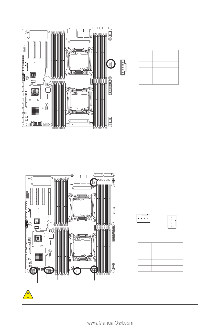
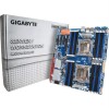
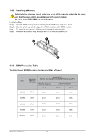
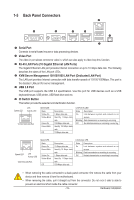
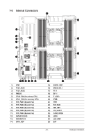
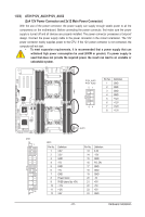
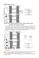
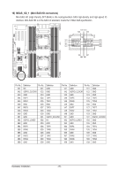
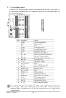
4) PMBUS (PMBus connector) Pin No. Definition 5 1 PMBus CLK 2 PMBus DATA 3 PMBus Alert 1 4 GND 5 3.3V Sense 5/6/7/8/9/10/11) CPU_FAN0/CPU_FAN1/SYS_FAN1/SYS_FAN2/SYS_FAN3/SYS_FAN4/ SYS_FAN5 (CPU Fan/System Fan Headers) The motherboard has two 4-pin CPU fan headers, and five 4-pin system fan headers. Most fan headers possess a foolproof insertion design. When connecting a fan cable, be sure to connect it in the correct orientation (the black connector wire is the ground wire). The motherboard supports CPU fan speed control, which requires the use of a CPU fan with fan speed control design. For optimum heat dissipation, it is recommended that a system fan be installed inside the chassis. CPU1_FAN CPU1_FAN CPU0_FAN SYS_FAN5 1 SYS_FAN1 SYS_FAN2 SYS_FAN3 SYS_FAN4 1 Pin No. 1 2 3 4 Definition GND +12V Sense Speed Control SYS_FANSY1 S_SFAYNS_2FASNY3S_FAN4 CPU0_FAN SYS_FAN5 • Be sure to connect fan cables to the fan headers to prevent your CPU and system from overheating. Overheating may result in damage to the CPU or the system may hang. • These fan headers are not configuration jumper blocks. Do not place a jumper cap on the headers. Hardware Installation - 23 -
-
 1
1 -
2
-
3
-
4
-
5
-
6
-
7
-
8
-
9
-
10
-
11
-
12
-
13
-
14
-
15
-
16
-
17
-
 18
18 -
 19
19 -
 20
20 -
 21
21 -
 22
22 -
 23
23 -
 24
24 -
 25
25 -
 26
26 -
 27
27 -
 28
28 -
29
-
30
-
31
-
32
-
33
-
34
-
35
-
36
-
37
-
38
-
39
-
40
-
41
-
42
-
43
-
44
-
45
-
46
-
47
-
48
-
49
-
50
-
51
-
52
-
53
-
54
-
55
-
56
-
57
-
58
-
59
-
60
-
61
-
62
-
63
-
64
-
65
-
66
-
67
-
68
-
69
-
70
-
71
-
72
-
73
-
74
-
75
-
76
-
77
-
78
-
79
-
80
-
81
-
82
-
83
-
84
-
85
-
86
-
87
-
88
-
89
-
90
-
91
-
92
-
93
-
94
-
95
-
96
-
97
-
98
-
99
-
100
-
101
-
102
-
103
-
104
-
105
-
106
-
107
-
108
-
109
-
110
-
111
-
112
-
113
-
114
-
115
-
116
-
117
-
118
-
119
-
120
-
121
-
122
 |
 |