Gigabyte MD80-TM0 Manual - Page 8
Force to Stop FRB Timer jumper
 |
View all Gigabyte MD80-TM0 manuals
Add to My Manuals
Save this manual to your list of manuals |
Page 8 highlights
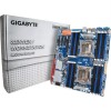
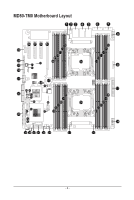
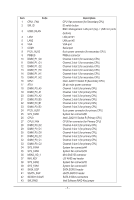
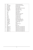
44 LED5 45 CASE_OPEN 46 ME_UPDATE 47 ME_RCVR 48 BIOS_PWD 49 BIOS_RCVR 50 SSATA0/1/2/3 51 F_USB3 52 FP_1 53 IPMB 54 BP_1 55 TPM 56 PCIE_1 57 PCIE_2 58 PCIE_3 59 PCIE_4 60 LED_BMC 61 BMC_FRB 62 S3_MASK 63 LSI_UART1 64 BUZZER1 65 CLR_CMOS 66 M2_SK 67 BAT 68 DIMM_P1_E0 69 DIMM_P1_E1 70 DIMM_P1_E2 71 DIMM_P1_F0 72 DIMM_P1_F1 73 DIMM_P1_F2 LSI firmware readiness LED Case open intrusion alert header ME update jumper ME recovry jumper Clearing Supervisor Password jumper BIOS recovery jumper SATA 3 6Gb/s connectors USB 3.0 header Front panel header IPMB connector HDD back plane board header TPM module connector PCI Express x8 slot PCI Express x8 slot PCI Express x8 slot PCI Express x16 slot BMC firmware readiness LED Force to Stop FRB Timer jumper S3 Power On Select jumper LSI UART header Buzzer Clear CMOS jumper M.2 slot Battery socket Channel 4 slot 0 (for secondary CPU) Channel 4 slot 1 (for secondary CPU) Channel 4 slot 2 (for secondary CPU) Channel 3 slot 0 (for secondary CPU) Channel 3 slot 1 (for secondary CPU) Channel 3 slot 2 (for secondary CPU) - 8 -
-
 1
1 -
2
-
 3
3 -
 4
4 -
 5
5 -
 6
6 -
 7
7 -
 8
8 -
 9
9 -
 10
10 -
 11
11 -
 12
12 -
 13
13 -
14
-
15
-
16
-
17
-
18
-
19
-
20
-
21
-
22
-
23
-
24
-
25
-
26
-
27
-
28
-
29
-
30
-
31
-
32
-
33
-
34
-
35
-
36
-
37
-
38
-
39
-
40
-
41
-
42
-
43
-
44
-
45
-
46
-
47
-
48
-
49
-
50
-
51
-
52
-
53
-
54
-
55
-
56
-
57
-
58
-
59
-
60
-
61
-
62
-
63
-
64
-
65
-
66
-
67
-
68
-
69
-
70
-
71
-
72
-
73
-
74
-
75
-
76
-
77
-
78
-
79
-
80
-
81
-
82
-
83
-
84
-
85
-
86
-
87
-
88
-
89
-
90
-
91
-
92
-
93
-
94
-
95
-
96
-
97
-
98
-
99
-
100
-
101
-
102
-
103
-
104
-
105
-
106
-
107
-
108
-
109
-
110
-
111
-
112
-
113
-
114
-
115
-
116
-
117
-
118
-
119
-
120
-
121
-
122
 |
 |