Gigabyte MD80-TM0 Manual - Page 28
F_USB3 USB 3.0 Header, IPMB IPMB Connector
 |
View all Gigabyte MD80-TM0 manuals
Add to My Manuals
Save this manual to your list of manuals |
Page 28 highlights
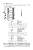
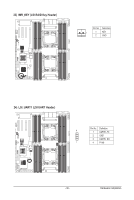
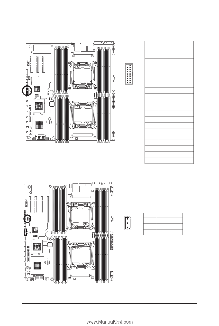
19) F_USB3 (USB 3.0 Header) The headers conform to USB 3.0 specification. Each USB header can provide two USB ports via an optional USB bracket. For purchasing the optional USB bracket, please contact the local dealer. Pin No. Definition 1 Power 2 IntA_P1_SSRX- 20 1 3 IntA_P1_SSRX+ 4 GND 5 IntA_P1_SSTX- 6 IntA_P1_SSTX+ 11 10 7 GND 8 IntA_P1_D- 9 IntA_P1_D+ 10 NC 11 IntA_P2_D+ 12 IntA_P2_D- 13 GND 14 IntA_P2_SSTX+ 15 IntA_P2_SSTX- 16 GND 17 IntA_P2_SSRX+ 18 IntA_P2_SSRX- 19 Power 20 No Pin 20) IPMB (IPMB Connector) 1 Pin No. Definition 1 Clock 2 GND 3 3 Data Hardware Installation - 28 -
-
 1
1 -
2
-
3
-
4
-
5
-
6
-
7
-
8
-
9
-
10
-
11
-
12
-
13
-
14
-
15
-
16
-
17
-
18
-
19
-
20
-
21
-
22
-
 23
23 -
 24
24 -
 25
25 -
 26
26 -
 27
27 -
 28
28 -
 29
29 -
 30
30 -
 31
31 -
 32
32 -
 33
33 -
34
-
35
-
36
-
37
-
38
-
39
-
40
-
41
-
42
-
43
-
44
-
45
-
46
-
47
-
48
-
49
-
50
-
51
-
52
-
53
-
54
-
55
-
56
-
57
-
58
-
59
-
60
-
61
-
62
-
63
-
64
-
65
-
66
-
67
-
68
-
69
-
70
-
71
-
72
-
73
-
74
-
75
-
76
-
77
-
78
-
79
-
80
-
81
-
82
-
83
-
84
-
85
-
86
-
87
-
88
-
89
-
90
-
91
-
92
-
93
-
94
-
95
-
96
-
97
-
98
-
99
-
100
-
101
-
102
-
103
-
104
-
105
-
106
-
107
-
108
-
109
-
110
-
111
-
112
-
113
-
114
-
115
-
116
-
117
-
118
-
119
-
120
-
121
-
122
 |
 |
Hardware Installation
- 28 -
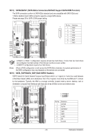
19) F_USB3 (USB 3.0 Header)
The headers conform to USB 3.0 specification. Each USB header can provide two USB ports via an
optional USB bracket. For purchasing the optional USB bracket, please contact the local dealer.
Pin No.
Definition
1
Power
2
IntA_P1_SSRX-
3
IntA_P1_SSRX+
4
GND
5
IntA_P1_SSTX-
6
IntA_P1_SSTX+
7
GND
8
IntA_P1_D-
9
IntA_P1_D+
10
NC
11
IntA_P2_D+
12
IntA_P2_D-
13
GND
14
IntA_P2_SSTX+
15
IntA_P2_SSTX-
16
GND
17
IntA_P2_SSRX+
18
IntA_P2_SSRX-
19
Power
20
No Pin
1
20
10
11
20) IPMB (IPMB Connector)
Pin No.
Definition
1
Clock
2
GND
3
Data
3
1