Haier DSF80B User Manual - Page 5
brown/red/black, N: Zero line blue, Ground, electrode, yellowish green, Hand-reset, temperature,
 |
View all Haier DSF80B manuals
Add to My Manuals
Save this manual to your list of manuals |
Page 5 highlights
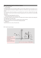
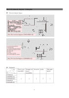
Electrical schematic diagram·Packing list „ Electrical schematic diagram (tcELNe(MREebyloT:H:e:mreTnco:Zl:t:pltwSroHereooerwnrLleondal/aiiersetHsvlteuroihiednarnren/eggGbdr(lper-baoeriwclpeunuksein)er)ed)et Note: This is the line diagram of DSF65/80MB I (E) L: Live wire (brown/red/black) N: Zero line (blue) E: Ground electrode (yellowish green) MT: Hand-reset temperature controller EH: Heating pipe RT: Sensor K1, K2 and K3: Switches BT: Constant temperature controller Note: This is the line diagram of DSF80MB II (E) „ Packing list QTY Product model Product model DSF80B (E) DSF80MB I (E) DSF80MB II (E) DSF65B (E) DSF65MB I (E) Electric water Hosepipe and Instruction packet heater(SET) shower nozzle(SET) 1 1 1 2 High-grade bracket 1 2
-
 1
1 -
 2
2 -
 3
3 -
 4
4 -
 5
5 -
 6
6 -
 7
7 -
 8
8 -
 9
9 -
 10
10 -
 11
11 -
12
-
13
 |
 |

Electrical schematic diagram
·
Packing list
Electrical schematic diagra
m
Packing list
Electric water
heater(SET)
Hosepipe and
shower
nozzle(SET)
Instruction
packet
High-grade
bracket
DSF80B (E)
DSF80MB I (E)
DSF80MB II (E)
DSF65B (E)
DSF65MB I (E)
1
1
1
2
1
2
L:
Live
wire
(brown/red/black)
N: Zero line (blue)
E:
Ground
electrode
(yellowish green)
MT:
Hand-reset
temperature
controller
EH: Heating pipe
RT: Sensor
Note: This is the line diagram of DSF65/80MB I (E)
L: Live wire (brown/red/black)
N: Zero line (blue)
E: Ground electrode (yellowish green)
MT: Hand-reset temperature controller
EH: Heating pipe
RT: Sensor
K1, K2 and K3: Switches
BT: Constant temperature controller
Note: This is the line diagram of DSF80MB II (E)
Product
model
QTY
Product
model