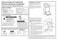
Haier QAS740RMSS Installation Instructions - Page 3
Wire Installation Ground Is Through The, Neutral Wire, Rear Trim Installation, Wire Installation - model
 |
View all Haier QAS740RMSS manuals
Add to My Manuals
Save this manual to your list of manuals |
Page 3 highlights
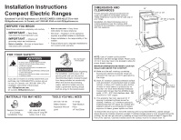
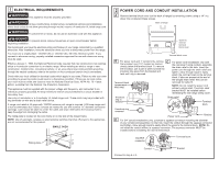
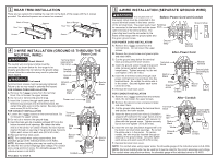
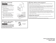
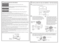
3 REAR TRIM INSTALLATION There are two options for installing the rear trim to the back of the range with the 4 screws provided. The attached spacers must never be removed. Back of Range Rear Trim Spacers Back of Range Rear Trim Spacers Screws Screws 4 3-WIRE INSTALLATION (GROUND IS THROUGH THE NEUTRAL WIRE) Power Cord WARNING Shock Hazard The neutral wire and ground strap must be Terminal block (appearance may vary) connected as shown below for the range to be properly grounded. Do not remove the ground strap. Failure follow this instruction may result in potential Neutral terminal shock hazard. WARNING Fire hazard Terminal block screws must be securely tightened. Ground strap Ground plate Failure to do so may result in potential fire hazard. FOR POWER CORD INSTALLATION A. Remove the 3 lower screws from the terminal Red or Black block. Do not loosen the upper screws. B. Do not cut or remove the ground strap. C. Insert the 3 screws through each power cord Power cord terminal ring and back into the terminal block. Be certain the white wire is in the center. Securely tighten each screw (35 to 50 in-lbs.) FOR CONDUIT INSTALLATION A. Loosen the 3 lower screws on the terminal block. Do not loosen the upper screws. Terminal block B. Do not cut or remove the ground strap. C. Insert the bare wire tip (insulation stripped 5/8") into the bottom terminal block openings. Be certain the white wire is in the center. On certain models, the wire must be inserted through an opening in the ground strap. Securely tighten each screw onto each wire (35 to 50 in-lbs.). Wire tips D. Reinstall terminal block cover. NOTE: For conduit wires using copper wires, the allowable gauge of the individual wires is 6-8 AWG. NOTE: Aluminum building wire may be used but it must Red or Black White be rated for the correct amperage and voltage. For conduit wires using aluminum wires, the allowable gauge of the individual wires is 4-8 AWG. Conduit PROCEED TO STEP 6. Red or Black White Conduit Red or Black 5 4-WIRE INSTALLATION (SEPARATE GROUND WIRE) WARNING The neutral wire of Before-Power Cord and Conduit the supply circuit must be connected to the neutral terminal located in the lower center of the terminal block. The power leads must Terminal be connected to the lower left and the lower block Ground strap right terminals of the terminal block. The grounding lead must be connected to the or frame of the range with the ground plate and the green ground screw. FOR POWER CORD INSTALLATION A. Remove the 3 lower screws from the Ground strap Neutral terminal terminal block. Do not loosen the upper screws. B. Remove the ground screw and ground plate After-Power Cord and retain them. C. Cut the ground strap below the terminal block and discard the lower section. D. Insert the ground screw through the ground plate (removed earlier) and back into the range frame. Tighten securely, but do not over-tighten (15 to 20 in-lbs.) E. Insert the 3 terminal screws through each power cord terminal ring and back into the terminal block. Be certain the white wire is in the center. Securely tighten each screw (35 to 50 in-lbs. F. Reinstall terminal block cover. FOR CONDUIT INSTALLATION Terminal block Red or Black White Ground screw Green or Bare Neutral terminal Ground plate (grounding to range) Red or Black A. Remove the 3 lower screws from the terminal block. Do not loosen the upper screws. After-Conduit B. Remove the ground screw and ground plate and retain them. C. Cut the ground strap below the terminal block and discard the lower section. Terminal block D. Insert the bare ground bare wire tip (insulation stripped 5/8") between the range frame and the ground plate (removed earlier) and secure it in place with the ground screw. Tighten securely, but do not over-tighten (15 to 20 in-lbs). Wire tips Red or Black Ground plate (grounding to range) Red or Black E. Insert the wire tips (insulation stripped 5/8") into the bottom terminal block openings. Be certain the white wire is in the center. On certain models, the wire must be inserted through an opening in the ground strap. Securely tighten each screw onto each wire (35 to 50 in-lbs.) White Ground screw Green or Bare F. Reinstall terminal block cover. NOTE: For conduit wires using copper wires, the allowable gauge of the individual wires is 6-8 AWG. NOTE: Aluminum building wire may be used but it must be rated for the correct amperage and voltage. For conduit wires using aluminum wires, the allowable gauge of the individual wires is 4-8 AWG.
-
 1
1 -
 2
2 -
 3
3 -
 4
4 -
 5
5 -
 6
6 -
 7
7 -
 8
8
 |
 |
