Harman Kardon A401 Owners Manual - Page 4
Speakers, Speaker
 |
View all Harman Kardon A401 manuals
Add to My Manuals
Save this manual to your list of manuals |
Page 4 highlights
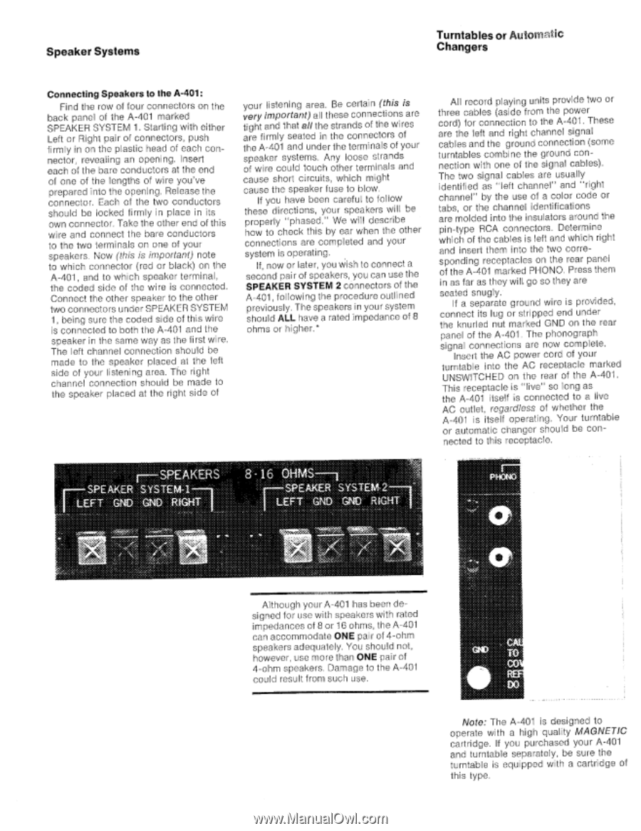
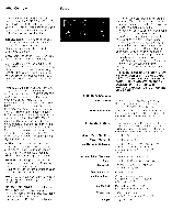
Speaker Systems Turntables or AlltO111AC Changers Connecting Speakers to the A-401: Find the row of four connectors on the back panel of the A-401 marked SPEAKER SYSTEM 1. Starting with either Left or Right pair of connectors, push firmly in on the plastic head of each connector, revealing an opening. Insert each of the bare conductors at the end of one of the lengths of wire you've prepared into the opening. Release the connector. Each of the two conductors should be locked firmly in place in its own connector. Take the other end of this wire and connect the bare conductors to the two terminals on one of your speakers, Now (this is important) note to which connector (red or black) on the A-401, and to which speaker terminal, the coded side of the wire is connected. Connect the other speaker to the other two connectors under SPEAKER SYSTEM 1, being sure the coded side of this wire is connected to both the A-401 and the speaker in the same way as the first wire. The left channel connection should be made to the speaker placed at the left side of your listening area. The right channel connection should be made to the speaker placed at the right side of your listening area. Be certain (this is very important) all these connections are tight and that all the strands of the wires are firmly seated in the connectors of the A-401 and under the terminals of your speaker systems. Any loose strands of wire could touch other terminals and cause short circuits, which might cause the speaker fuse to blow. If you have been careful to follow these directions, your speakers will be properly "phased." We will describe how to chock this by ear when the other connections are completed and your system is operating. If, now or later, you wish to connect a second pair of speakers, you can use the SPEAKER SYSTEM 2 connectors of the A-401, following the procedure outlined previously. The speakers in your system should ALL have a rated impedance of 8 ohms or higher.* All record playing units provide two or three cables (aside from the power cord) for connection to the A-401. These are the left and right channel signal cables and the ground connection (some turntables combine the ground connection with one of the signal cables). The two signal cables are usually identified as "left channel" and "right channel" by the use of a color code or tabs, or the channel identifications are molded into the insulators around the pin-type RCA connectors. Determine which of the cables is left and which right and insert them into the two corresponding receptacles on the rear panel of the A-401 marked PHONO. Press them in as far as they will go so they are seated snugly. If a separate ground wire is provided, connect its lug or stripped end under the knurled nut marked GND on the rear panel of the A-401. The phonograph signal connections are now complete. Insert the AC power cord of your turntable into the AC receptacle marked UNSWITCHED on the rear of the A-401. This receptacle is "live" so long as the A-401 itself is connected to a live AC outlet, regardless of whether the A-401 is itself operating. Your turntable or automatic changer should be connected to this receptacle. - SPEAKERS M.SPEAKER SYSTEM-1 T GND CND RIGHT 8 16 OHMS SPEAK-E1R SYSTEM-2. GNID GNID RICH OM. 7':4. 1MM:i Although your A-401 has been designed for use with speakers with rated impedances of 8 or 16 ohms, the A-401 can accommodate ONE pair of 4-ohm speakers adequately. You should not, however, use more than ONE pair of 4-ohm speakers. Damage to the A-401 could result from such use. Note: The A-401 is designed to operate with a high quality MAGNETIC cartridge. If you purchased your A-401 and turntable separately, be sure the turntable is equipped with a cartridge of this type.
-
 1
1 -
 2
2 -
 3
3 -
 4
4 -
 5
5 -
 6
6 -
 7
7 -
 8
8 -
 9
9 -
 10
10
 |
 |