Harman Kardon A401 Owners Manual - Page 5
Tuners, Connecting, Equipment, Other, TUNER, equipment., 0UT:i, RIGHT
 |
View all Harman Kardon A401 manuals
Add to My Manuals
Save this manual to your list of manuals |
Page 5 highlights
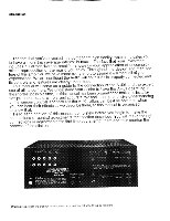
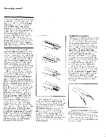
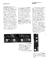
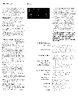
Tuners Connecting Tape Equipment Other Equipment Most tuners utilize pin type RCA receptacles as output connectors. Your tuner may also have a chassis ground terminal. These connectors are generally placed on the rear panel of tuners. Locate them on your unit. If the output connectors are other than pin type RCA receptacles, it will be necessary for you to obtain a mating adapter from your dealer. Connect a cable having pin type RCA male plugs between the LEFT channel OUTPUT receptacle of your tuner and the LEFT TUNER INPUT receptacle of the A-401. Similarly connect a cable between the RIGHT channel OUTPUT receptacle of your tuner and the RIGHT TUNER INPUT receptacle of the A-401. Push the plugs in all the way so they are firmly seated, making good electrical contact. Connect an insulated wire between •• ground (GND) terminal on the A-401 and the similar connection on your tuner. If your tuner lacks a terminal, connection may be made to an unpainted screw head. Many dealers stock cables which contain the two shielded signal cables and ground lead in a single molded assembly. A cable of this type makes for a very neat, convenient installation. The AC power cable of your tuner may be plugged into the switched 120 VAC receptacle on the A-401. In this case the tuner will be activiated by the front panel power switch of the A-401. The A-401 provides facilities for both the recording and playback of tape programs to and from open-reel, cassette, or eight-track cartridge equipment. Using the signal cables provided with your tape deck or recorder, recordings can be made by connecting the left and right channel TAPE receptacles (under the bracket labeled OUTPUTS) on the rear panel of the A-401 to the corresponding input receptacles of your tape equipment. If your open-reel or cassette equip- ment offers true off-tape monitoring facilities, the left and right channel output receptacles of your tape equipment should be connected to the corresponding TAPE MONITOR recep- tacles under the bracket labeled INPUTS. Most cassette recorders and many open-reel units do not offer true tape monitor capability. However, the outputs of these machines may still be connected to the TAPE MONITOR receptacles of the A-401. Tape equipment capable of playback only, can be connected to either the TAPE MONITOR or AUX receptacles of the A-401. The choice here wil l be affected by your desire or need to reserve the AUX inputs of the A-401 for use as explained below. A pair of auxiliary inputs is available at the rear of the A-401 for the connection of any "high level" output equipment. A special tuner for long wave, marine, aircraft, or citizen's bands, etc. may be connected - or you may choose to connect a second tape recorder or the output of the audio section of a television receiver. Any number of choices is available. Consult your dealer for information as to what equipment is compatible with the parameters of the AUX inputs of the A-401. If you have not used the SWITCHED AC OUTLET for a tape recorder, you can use it for accessory equipment. The connections to the rear panel of the A-401 are now complete. Insert its AC power cord into a convenient wall outlet and place the A-401 in its final position in your listening room. TU. N: EN.R:•P::.:::U:.• TS. . 4 G,3J-- T.puTs 7 . -• . •• • . ' em4e ON1 OR 0UT:.i.p....U. T% . . ::l M The remaining SWITCHED AC OUTLET on the rear of the A-401 may be used to provide power for your tape deck or recorder. This outlet is "live" only when the A-401 is itself operating. If you wish, the power switch of your tape equipment may be left in the "on" position - power to it would then be controlled by the POWER SWITCH of the A-401. If you use this outlet, be sure the recorder's drive system is disengaged before you switch the A-401 off, RIGHT . . AC 1.:7-Cv•v:,..":• -ii VAX 200%,i• SwiTCHED UNSV cHEE, .... .
-
 1
1 -
 2
2 -
 3
3 -
 4
4 -
 5
5 -
 6
6 -
 7
7 -
 8
8 -
 9
9 -
 10
10
 |
 |