Harman Kardon AVR 520 Owners Manual - Page 10
Rear Panel Connections - remote codes
 |
View all Harman Kardon AVR 520 manuals
Add to My Manuals
Save this manual to your list of manuals |
Page 10 highlights
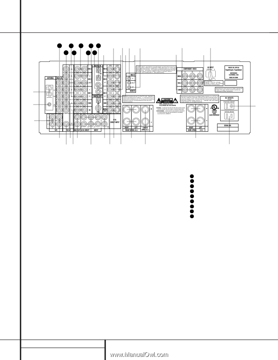
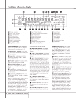
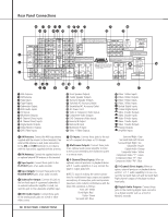
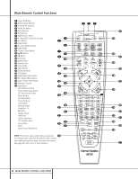
Rear Panel Connections 39 37 35 33 31 j hf d 38 36 34 32 k ig e b c · a ¡ ™ ° £ ¢ §• ,¤ › ∞¶ ª ⁄‹ fi ¡ AM Antenna ™ FM Antenna £ Tape Inputs ¢ Tape Outputs ∞ Subwoofer Output § DVD Audio Inputs ¶ CD Inputs • Multiroom Outputs ª 6-Channel Direct Inputs , 8 Channel Direct Inputs ⁄ Digital Audio Outputs ¤ Video Monitor Outputs ‹ DVD Video Inputs › Front Speaker Outputs fi Center Speaker Outputs fl Surround Speaker Outputs ‡ Switched AC Accessory Outlet ° Unswitched AC Accessory Outlet · AC Power Cord a Video 2 Component Video Inputs b Component Video Outputs c DVD Component Video Inputs d Remote IR Output e Remote IR Input f Multiroom IR Input g Video 1 Video Outputs ¡ AM Antenna: Connect the AM loop antenna supplied with the receiver to these terminals. If an external AM antenna is used, make connections to the AM and GND terminals in accordance with the instructions supplied with the antenna. ™ FM Antenna: Connect the supplied indoor or an optional external FM antenna to this terminal. £ Tape Inputs: Connect these jacks to the PLAY/OUT jacks of an audio recorder. ¢ Tape Outputs: Connect these jacks to the RECORD/INPUT jacks of an audio recorder. ∞ Subwoofer Output: Connect this jack to the line-level input of a powered subwoofer. If an external subwoofer amplifier is used, connect this jack to the subwoofer amplifier input. § DVD Audio Inputs: Connect these jacks to the analog audio jacks on a DVD or other video source. ¶ CD Inputs: Connect these jacks to the output of a compact disc player or CD changer. • Multiroom Outputs: Connect these jacks to an optional audio power amplifier to listen to the source selected by the mulitroom system in a remote room. ª 6-Channel Direct Inputs: When an optional, external processor or playback device with 5.1 audio capability is in use, connect the player's output jacks here. NOTE: To assist in making the correct connections for multichannel input output and speaker connections, all connection jacks and terminals have been color coded in conformance with the latest CEA standards as follows: Front Left: White Front Right: Red Center: Green Surround Left: Blue fl ‡ h Video 1 Video Inputs i Video 2 Video Outputs j Video 3 Video Inputs k Video 2 Video Inputs 31 Optical Digital Inputs 32 Coaxial Digital Inputs 33 Video 2 Audio Outputs 34 Video 2 Audio Inputs 35 Video 3 Audio Inputs 36 Video 1 Audio Inputs 37 Video 1 Audio Outputs 38 Preamp Outputs 39 Amplifier Inputs Surround Right: Gray Surround Back Left: Brown Surround Back Right: Tan Subwoofer: Purple Digital Audio: Orange Composite Video: Yellow Component Video "Y": Green Component Video "Pr": Red Component Video "Pb": Blue , 8-Channel Direct Inputs: When an option, external processor or playback device with 6.1 or 7. 1 audio capability is in use, connect the Surround Back Left and Surround Back Right channel outputs of the player to these input jacks. ⁄ Digital Audio Outputs: Connect these jacks to the matching digital input connector on a digital recorder such as a CD-R or MiniDisc recorder. 10 REAR PANEL CONNECTIONS
-
 1
1 -
2
-
3
-
4
-
 5
5 -
 6
6 -
 7
7 -
 8
8 -
 9
9 -
 10
10 -
 11
11 -
 12
12 -
 13
13 -
 14
14 -
 15
15 -
16
-
17
-
18
-
19
-
20
-
21
-
22
-
23
-
24
-
25
-
26
-
27
-
28
-
29
-
30
-
31
-
32
-
33
-
34
-
35
-
36
-
37
-
38
-
39
-
40
-
41
-
42
-
43
-
44
-
45
-
46
-
47
-
48
-
49
-
50
-
51
-
52
-
53
-
54
-
55
-
56
 |
 |