Harman Kardon AVR 520 Owners Manual - Page 6
Front Panel Controls - setup
 |
View all Harman Kardon AVR 520 manuals
Add to My Manuals
Save this manual to your list of manuals |
Page 6 highlights
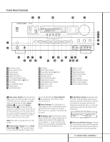
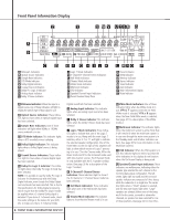
Front Panel Controls was in use. Each subsequent press selects the next DTS mode in the following order: DTS-ES 6.1 DISCRETE DTS-ES 6.1 MATRIX DTS 5.1 7 Logic 7 Mode Selector /‹ Button: This button has two functions: In normal use, press it to select one of the Logic 7 modes. When an adjustment is being made using using the Channel Select Ù or Digital Select Û buttons, this button may be pressed to scroll through the available options. 8 Tone Mode: Pressing this button enables or disables the Bass and Treble tone controls. When the button is pressed so that the words TONE IN appear in the Main Information Display ˜, the settings of the Bass and Treble Ú controls may be used to adjust the output signals. When the button is pressed so that the words TONE OUT appear in the Main Information Display ˜, the output signal will be "flat," without any bass or treble alteration, no matter how the actual Bass and Treble Controls Ú are adjusted. 9 Surround Mode Selector: Press this button to change the surround mode by scrolling through the list of available modes. Note that depending on the type of input, some modes are not always available. (See page 26 for more information about surround modes.) ) Tuning Selector: Press the left side of the button to tune lower-frequency stations and the right side of the button to tune higher-frequency stations. When a station with a strong signal is reached, the TUNED Indicator W will be lit in the Main Information Display ˜ . To tune manually, tap the button lightly and note that the tuner will step up one frequency increment per button press. When the button is held for a few seconds you will note that the unit will quickly search the frequency band. Release it once the fast tuning starts; the tuner will automatically scan for the next station with an acceptable signal and then stop. ! Tuner Band Selector: Pressing this button will automatically switch the AVR 520 to the Tuner mode. Pressing it again will switch between the AM and FM frequency bands. (See page 31 for more information on the tuner.) @ Set Button: When making choices during the setup and configuration process, press this button to enter the desired setting as shown in the Main Information Display ˜ into the AVR 520's memory. # Preset Station Selector: Press this button to scroll up or down through the list or stations that have been entered into the preset memory. (See page 32 for more information on tuner programming.) $ Stereo Mode Selector /› Button: Pressing this selector button cycles through the stereo modes, and it is also used to turn off all surround processing and place the unit in a traditional two-channel Stereo mode. The first press selects 5-Channel Stereo, the next press selects 8-Channel Stereo, and the third press selects "SURROUND OFF," which is true Stereo. % Input Source Selector: Press this button to change the input by scrolling up or down through the list of input sources. ^ FM Mode Selector: Press this button to select Auto or Manual tuning. When the button is pressed so that the AUTO Indicator X lights, the tuner will search for the next station with an acceptable signal when the Tuning Selector )ué is pressed. When the button is pressed so that the AUTO Indicator X is not lit, each press of the Tuning Selector )ué will increase the frequency. (See page 31 for more information on using the tuner.) & DTS Neo:6 Mode Selector: Pressing this selector button cycles the AVR through the various DTS Neo:6 modes, which extract a fivechannel surround field from two-channel program material. The first press selects the last DTS Neo:6 surround mode that was in use, and each subsequent press selects the next mode in the following order: DTS Neo:6 MUSIC DTS Neo:6 MOVIES DTS Neo:6 EMULATION * Digital Optical 3 Input: Connect the optical digital output of an audio or video product to this jack. When the input is not in use, be certain to keep the plastic cap installed to avoid dust contamination that might degrade future performance. ( Input/Output Status Indicator: These LED indicators will normally light green to show that the front panel Video 4 A/V Ô jacks or the Coaxial 3 Digital Ó jacks are operating as inputs. When either of these jacks has been configured for use as an output, the indicator will turn red to show that the jack may be used for recording. (See page 20 for more information on configuring the front panel jacks as outputs, rather than inputs.) Ó Digital Coax 3 Jack: This jack is normally used for connection to the output of portable audio devices, video game consoles or other products that have a coax digital jack. It may also be configured as an output jack, to feed a digital signal to a CD-R, MiniDisc or other digital recording device. (See page 20 for information on configuring the Digital Coax 3 Jack as an output.) Ô Video 4 Input Jacks: These audio/video jacks may be used for temporary connection to video games or portable audio/video products such as camcorders and portable audio players. Bass Control: Turn this control to modify the low-frequency output of the left/right channels by as much as ±10dB. Set this control to a suitable position for your taste or room acoustics. Ò Balance Control: Turn this control to change the relative volume for the front left/right channels. NOTE: For proper operation of the surround modes, this control should be at the midpoint, or "12 o'clock", position. Ú Treble Control: Turn this control to modify the high-frequency output of the left/right channels by as much as ±10dB. Set this control to a suitable position for your taste or room acoustics. Û Digital Select Button: When playing a source that has a digital output, press this button to select between the Optical * 33 and Coaxial Ó 34 Digital inputs. (See page 29 for more information on digital audio.) Ù Channel Select Button: Press this button to begin the process of trimming the channel output levels using an external audio source. (For more information on output level trim adjustment, see page 32.) 6 FRONT PANEL CONTROLS
-
 1
1 -
 2
2 -
 3
3 -
 4
4 -
 5
5 -
 6
6 -
 7
7 -
 8
8 -
 9
9 -
 10
10 -
 11
11 -
 12
12 -
13
-
14
-
15
-
16
-
17
-
18
-
19
-
20
-
21
-
22
-
23
-
24
-
25
-
26
-
27
-
28
-
29
-
30
-
31
-
32
-
33
-
34
-
35
-
36
-
37
-
38
-
39
-
40
-
41
-
42
-
43
-
44
-
45
-
46
-
47
-
48
-
49
-
50
-
51
-
52
-
53
-
54
-
55
-
56
 |
 |