Harman Kardon CIT25 Owners Manual - Page 8
Filter
 |
View all Harman Kardon CIT25 manuals
Add to My Manuals
Save this manual to your list of manuals |
Page 8 highlights
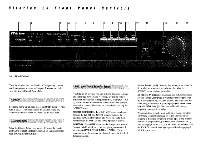
5ubsonlc Filter The SUBSONIC (22) circuit helps control the acoustic consequences of warped records and turntable resonance. If you can see your speaker's woofer cones visibly flutter in and out when you play a record, subsonic frequencies are present. While directly inaudible, subsonics can rob amplifier power, cause intermodulation distortion at audible frequencies and actually damage woofer cones if the movement is violent enough. The Citation 25's SUBSONIC filter circuit reduces sub-bass frequencies at 6dB per octave below 15 Hz. Audible bass response will not be significantly affected by this action, so you may leave this button pressed in whenever you play phonograph records. While the subsonic filter circuit cuts inaudible (but potentially destructive) sub-bass frequencies, the HI CUT filter (23) can be used to reduce audible (but unpleasant) high frequency hiss. This circuit reduces frequencies above 6000 Hz at the rate of 6 dB/octave. Since your range of hearing extends as high as 20,000Hz, the HI CUT filter should only be used on video or audio sound sources winch have a noticeably high level of noise. Make sure the button is in its OUT position when listening to music or video sound which is relatively hiss-free. 0 The MONO button (24) combines left and right channel signals and routes their sum to both power amplifier channels. It has several purposes. The most obvious application for this switch is with mono records, such as old 45's, 78's and many excellent classical I.P's you may have collected. NOTE: It is not necessary, however, to engage the Mono button when listening to Compact Discs of older albums which have retained the original mono format. Another use is with the input from a mono VCR. Engaging the MONO button will route the sound to both left and right speakers. You can also use the MONO button as a means of testing speaker phase during system hook-up. After connecting your speakers to their power amplifier, play a stereo record with a vocal or instrumental that images in the center between the two speakers. While sitting in a normal listening position in front of and between the speakers, have someone switch the MONO button on the Citation 25 in and out. There should be no change in the intensity or imaging of the vocal or instrumental. If there IS a change, one of the speakers has been connected out of phase, which results in poor stereo imaging and a diminution of bass. Re-check the polarity of your speaker-toamplifier connections. 0cartridge 6'elector To the right of the MONO button is the MOVING MAGNET! MOVING COIL cartridge input selector (25). The normal (OUT) position selects the Citation 25's input for regular moving magnet cartridges and high output moving coil cartridges with an output rating of at least 2.2mV. The "IN" position switches to the moving coil inputs and engages a special MC step-up amplifier stage. Capacitance and resistance trim adjustments are also provided on the Citation 25's rear panel to further optimize MM/MC performance. Note that you can connect both MM and MC cartridge inputs to the Citation 25 and use this selector button to switch between them. Ojitput This set of selectors mirrors the configuration of the playback source selector buttons on the upper front panel. However, they select the source for RECORDING, rather than listening. As with the playback selectors, the SOURCE (30) button activates the next five record sources: AN 1 (31), NV 2 (32), CD (33), TUNER (34) and PHONO (35). This system lets you: 1) record video and audio from TV, LaserDisc or CDV (connected to the A/V 1 & A/V 2 sources) unto one OR two VCR's. 2) dub video and audio from one VCR to another. 3) record audio from tuner, CD, tape or turntable onto your audio cassette recorder. 4) record audio from those sources onto VHS Hi-Fi video tape. It is important to note that once a RECORD SOURCE has been selected (using buttons 26-35), this signal is sent to all connected components which are capable of recording. To choose which of them to record with, set those units to their RECORD mode. • For example, if you have a stereo 'EV hooked up to A/V 1, pressing RECORD OUTPUT AN 1 (31) will send video and audio to VCR 1 and VCR 2 (and audio only to TAPE I and TAPE 2). If you wish to make one videocassette copy, simply set your VCR 1 to record. If you wish to make TWO copies, activate VCR 1 and VCR 2. Note that you could also make one or two audio soundtrack copies at the same time with TAPE 1 and TAPE 2, since the TV sound is also automatically routed to them.
-
 1
1 -
2
-
 3
3 -
 4
4 -
 5
5 -
 6
6 -
 7
7 -
 8
8 -
 9
9 -
 10
10 -
 11
11 -
 12
12 -
 13
13 -
14
-
15
-
16
-
17
-
18
-
19
-
20
 |
 |
