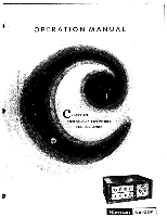
Harman Kardon CITATION I Owners Manual - Page 6
outputs, input.
 |
View all Harman Kardon CITATION I manuals
Add to My Manuals
Save this manual to your list of manuals |
Page 6 highlights
Installati on The Citation I may be easily installed in your cabinet by following the simple instructions on the mounting template supplied. Alternatively, a furniture-finished hardwood enclosure is available from your dealer as an optional extra. Power Amplifier Connection The Citation I Preamplifier was specifically designed for operation with the Citation II Stereo Power Amplifier. However, it is eminently suited to driving any other stereo power amplifier, or a pair of monophonic power amplifiers. If two monophonic amplifiers are used, it is strongly suggested that they be a matched pair. Two pairs of preamplifier output receptacles are provided. These can be used to drive two entirely separate stereo power amplifiers in different locations. Shielded leads with standard plugs are used for ma ing the connec- tions. These can be obtained from your dealer in the lengths required. Because the Citation I uses low-impedance. anode followers at the outputs, the power amplifier may be placed in any location up to forty feet from the Cita- tion I. When using the Citation II Power Amplifier, connect from the Citation I CHANNEL A OUTPUT receptacle (either one) to the Citation II CHANNEL A INPUT. Then connect a second shielded lead from either of the Citation I CHANNEL B OUTPUT receptacles to the Citation II CHANNEL B INPUT. The remaining pair of Citation I output receptacles, A and B, can be used to drive a second stereo amplifier. If you are using a pair of monophonic amplifiers with the Citation I, connect one of the preamplifier CHANNEL A outputs and one of the CHANNEL B outputs to the inputs of these amplifiers. If "center fill" is required in your stereo system, a monophonic amplifier can be added. Simply connect a shielded lead from the Citation I receptacle marked CENTER CHANNEL AMP OUT to the input of the thirdchannel amplifier. This channel can also be used to provide remote monophonic operation. Follow the instructions provided with your amplifier to connect your speakers. Do not turn on the equipment until you have made these connections. Tape Head Playback Connection Connect a pair of shielded leads from your stereo tape deck to the A and B TAPE HD input receptacles on the INPUT CHANNEL strip at the rear of the Citation I. A monophonic tape deck can be connected to either of these inputs. If your tape player has its own preamplifier, do not use the TAPE HD inputs. The next paragraph describes this type of connection. Tape Recorder Playback Connection Connect the outputs of your stereo tape recorder to the A and B TAPE AMP input receptacles on the IN- PUT CHANNEL strip at the rear of the Citation I. The output of a monophonic tape recorder can be connect- ed to either the A or B TAPE AMP input. Tape Recorder Recording Connection Provision is made on the Citation I to permit the recording of anyprogram material. Connect the left input of your stereo tape recorder to the TAPE OUT receptacle A on the Citation I, and connect the right recorder input to TAPE OUT receptacle B. A monophonic recorder can be connected to either of the TAPE OUT receptacles. These connections should be kept as short as possible to avoid loss of treble response. Tuner Connection Connect a pair of shielded leads from the AM and FM output receptacles of your stereo tuner to the Cita- tion I TUNER Channel A and B receptacles. The FM lead is normally plugged into the Channel A tuner receptacle, the AM lead being connected to the Channel B receptacle. The same procedure applies if you are using separate AM and FM tuners. If you are using a monophonic AM/FM tuner, connect it to the Channel A TUNER receptacle. Multiplex is a form of FM stereo broadcasting where both channels are transmitted by one FM station. In addition to an FM tuner, a multiplex adaptor is necessary. For hookup information consult your adaptor instruction book.
-
 1
1 -
 2
2 -
 3
3 -
 4
4 -
 5
5 -
 6
6 -
 7
7 -
 8
8 -
 9
9 -
 10
10 -
 11
11 -
 12
12 -
13
-
14
-
15
 |
 |
