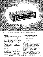
Harman Kardon FM100 Owners Manual - Page 2
Connections
 |
View all Harman Kardon FM100 manuals
Add to My Manuals
Save this manual to your list of manuals |
Page 2 highlights
VENTILATION AU electrical equipment generates heat which must he allowed to escape. Although the Counterpoint II is well-ventilated in itself, sufficient space should be allowed around it to permit free air flow. If it is placed in a bookcase, it should be located well toward the front, to provide as much clearance as possible at the rear. DO NOT place books or other objects on top of the Counterpoint H. Covering the perforated metal cage will prevent proper air flow and will result in sharply reduced component and tube life. POWER REQUIREMENTS Plug the AC power cord into any outlet furnishing 117 volts, 50 or 60 cycles house current. The exact voltage is relatively unimportant and may vary between 105 to 125 volts. Be sure, however, that you have a 50 or 60 cycle AC power source. ELECTRICAL CONNECTIONS FM Antenna: Due to the extremely high FM sensitivity of the Counterpoint II, the 48" piece of wire furnished with the set will be sufficient antenna for all but the must difficult locations. One end of this wire should be fastened to the "A" terminal of the Antenna Terminal Strip, the other end left free and extended as may be convenient. It may be tacked or stapled to the rear of the bookcase or equipment cabinet if necessary. If, for some reason, it is necessary to utilize other FM antenna types, we have listed for your convenience the following suggestions: 1. Special outdoor FM antennas may be used. These come in various types. For extremely difficult locations an in-line Yagi cut for the FM band or equivalent may be necessary. For reception of FM stations scattered in many directions, a nondirectional antenna may be used. This nondirectional type is known as a double dipole and consists of two folded dipoles placed at right angles to each other. 2. Your present TV antenna may he used to obtain a maximum FM signal. A special antenna coupler or knife switch should be used when joining the FM line to the television antenna. If using a 300-ohm TV wire it should be connected to the "G" and "A" terminal on the Antenna Terminal Strip. Output Two receptacles will be found at the rear of the chassis marked "Output" and "Multiplex." For your convenience in connecting the tuner to the amplifier you will find a 36" shielded cable packed with the Counterpoint II. Plug one end of this cable into the "Output" receptacle and the other end into the appropriate input receptacle of the amplifier. Since the output circuit of the tuner uses a cathode follower this cable may be extended to any reasonable length without deterioration of tone quality. The "Multiplex" jack is taken directly from the detector output and is to he connected to multiplex equipment only. The Multiplex output jack bypasses 2 the deemphasis network and will give a 13.8 db rise at 10,000 cycles. OPERATION The Harman-Kardon Counterpoint H has only three operating controls. The Tuning Knob to the right selects the desired FM station. The Concentric Control at the left is two controls in one. The inner knob turns the power on and off and adjusts the Automatic Noise Gate action. The outer knob controls the Automatic Frequency Control (AFC) action. Maximum AFC and ANG action is obtained in the extreme clockwise position. TECHNICAL EXPLANATION OF THE CONTROLS Automatic Noise Gate Control: Automatic Noise Gate action (ANG) permits tuning between stations without the cnstomary FM interstation hiss and adds considerably to the enjoyment of FM reception. The ANG control may be set for minimum interstation noise as required in your location. Advancing the control clockwise gradually increases this action and at the extreme clockwise position the ANG has maximum effect. The continuously variable feature of this control enables you to select the degree of ANG action without cancelling out wanted stations. Proper adjustment of the ANG control is made by first turning the control completely counterclockwise and then advancing clockwise to the point where interstation background noise cuts out. At this point even the weakest station will operate the noise gate. Turning the control further clockwise will require an increasingly stronger signal to operate the noise gate. Tuning Meter: The precise Harman-Kardon tuning meter op) crates whether AFC is in the circuit or not. When the Counterpoint II is tuned completely off any station, the tuning meter will point to zero. As you tune through a station, the needle will swing to one side, then to zero, then to the other side, and as you tune away from the station, back to zero. The tuning is proper only when the needle points to approximately zero. For precise meter adjustment see Behind The Chassis Controls section for adjustment procedure. Automatic Frequency Control (AFC): FM Broadcasting, by its, very nature, eliminates almost all natural and `man-made static. However, the characteristics of FM which make this possible also make for problems in tuning. The Harman-Kardon Counterpoint II incorporates an effective Automatic Frequency Control (AFC) circuit that overcomes these problems and insures proper tuning even if the manual tuning is not accurately done. The following experiment will lead to an understanding of AFC, and the fuller enjoyment of the Counterpoint II. First, rotate the "AFC" control to the extreme clockwise position. Now tune across the scale. Note how the stations "pop" into place, one after the other. Now tune to any station, preferably one with a musical program. Turn the "AFC" control counterclockwise as far as possible. This defeats the AFC. Tune slowly through the station from left
-
 1
1 -
 2
2 -
 3
3 -
 4
4
 |
 |
