Harman Kardon FM100 Owners Manual - Page 3
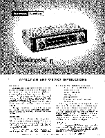
Counterpoint
 |
View all Harman Kardon FM100 manuals
Add to My Manuals
Save this manual to your list of manuals |
Page 3 highlights
to right. Notice that there are three points where the station sounds clean, interspersed with points of distorted sound. The middle clean-sounding point is the proper tuning position for the best tone quality with minimum noise and interference. At this point the tuning meter will indicate proper tuning. Tune slightly away from the proper tuning position, until the sound is distorted. Note that the tuning meter will indicate improper tuning. Now reactivate the AFC by turning the "AFC" knob to the right. You will notice that the sound clears up and the proper tuning indication is restored, as if the receiver had been manually retuned. Actually, the tuning has been electrically readjusted by the operation of the AFC circuit, which automatically retunes the electronic circuits to the center of the station channel. In order to take maximum advantage of the benefits of AFC, it is suggested that tuning be done with AFC off, to render a more precise indication of the tuning meter. When AFC is then turned on, the tuning will be improved by a ratio_of 10 to 1. This procedure is especially recommended in those areas where a weak station is found close to a strong station. Under this condition, the AFC may tend to reach for the strong station and completely skip over the weak one. If the weak station is tuned in without AFC, it will be locked in when the AFC is turned on. Another procedure might be to find that setting of the AFC control which provides the exact amount of AFC action for most convenient tuning in your location. To do this, tune to a portion of the dial where a strong station is found immediately adjacent to a weak station. (If this situation cannot be found in your location, leave the AFC control at maximum.) Now tune slowly through both stations, from the direction of the strong station. If the AFC control is set too high, the stronger station may be held until the tuning is past the weak station. Adjust the AFC so that when the stronger station pops out, the weaker station appears. The professional feature of variable AFC enables the user to select the amount of AFC desired at any time according to location and personal preference. BEHIND THE CHASSIS CONTROLS Output Level Control: The output level of the Counterpoint II may be adjusted to suit the input rec iremtn'ts of the amplifier or to balance the volume of another program source (such as a record player). The Output Level Control located to the right of the AC connection should be set at maximum if it is not desired to balance volume levels. FM Rumble Filter: Many broadcast stations transmit a certain amount of low frequency rumble that may be produced by the records or turntables used at the station. This low frequency signal is often disturbing in a high quality system and the Counterpoint II incorporates a rumble filter which eliminates this unwanted signal by reducing response below 50 cycles. This filter is controlled by a slide switch on the rear of the chassis. Meter Adjustment Control: A meter balancing control is incorporated in the Counterpoint II so that the meter may be precisely set. This control is located on the back panel slightly to the left and above the Output Jack. To adjust, tune between stations and turn the control until the needle points to the center of the scale (Zero Mark). MAINTENANCE AND REPAIR In some installations, hum may be encountered due to a voltage difference between the amplifier, tuner and record changer chassis. This may be eliminated by reversing one or all of the AC power plugs. Simply reverse one at a time until improvement is experienced. Due to the conservative design and high quality components of the Counterpoint II, no routine maintenance other than yearly tube-testing is required. Should trouble develop, however, only the most qualified serviceman should be employed, as special equipment and training is required to properly service high fidelity equipment. This instruction booklet contains diagrams and other information needed by your repairman. It should be kept available for his use. CHANGING PILOT LIGHTS AND TUBES: In order to change tubes or pilot lights in this unit remove the 7 screws holding the cage and slide cage off. Tubes are then exposed and can be removed. Make certain that excessive pressure is not applied to the , printed circuit board or components. To change the right hand pilot light turn the tuning condenser until it is completely closed. The pointer will then be at the extreme left of the dial. The screw holding the light assembly at the right side can now be loosened and the assembly pushed straight back thus making the pilot lamp accessible. To remove the left pilot light remove the screw holding the assembly and push the assembly straight back while turning to the right. To reinsert the pilot light assemblies merely reverse the above procedure. STACKING THE COUNTERPOINT II Rubber pads are included in the event that it is desired to stack the tuner on top of the Harman-Kardon Rondo amplifier with a minimum of space between. Their correct use is as follows: 1. Remove cage. 2. Remove bottom plate. 3. Remove both runners from the bottom plate. 4. Now replace bottom plate and cage. 5. Remove safety paper from each pad and press firmly into place on bottom plate in 4 corners, approximately evenly spaced. WARRANTY We warrant each Counterpoint II, Model FM-100 to be free from defects in material and workmanship under normal use and service, and in accordance with the conditions herein below set forth, for a period of 1 year from date of delivery to the (anginal purchaser, and agree to replace or repair any part or parts, except tubes which are under manufacturer's 90-day warranty, returned to us within said 1 year, with transportation 3
-
 1
1 -
 2
2 -
 3
3 -
 4
4
 |
 |
