Harman Kardon HK395I Owners Manual - Page 4
Antennas
 |
View all Harman Kardon HK395I manuals
Add to My Manuals
Save this manual to your list of manuals |
Page 4 highlights
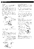
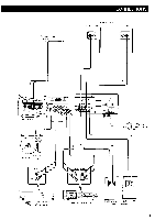
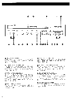
ANTENNAS FM Antenna If experiencing poor FM reception while using the accessory antenna, the use of an outdoor antenna exclusively for FM reception is likely to improve FM reception. The connecting wire between the antenna and the antenna input terminal is called a feeder. Most feeders are 300 Ohm parallel or 75 Ohm coaxial cables. We recommend type 3C2V or 5C-2V 75 Ohm coaxial cable to be used with this unit to enable it to perform to its fullest capacity. The coaxial cable has a stronger resistance against loss and interference compared to a parallel feeder. If there is a lot of noise while receiving an FM broadcast, we recommend that you make a ground connection. Connect one end of a thick wire to the antenna GND terminal and wind the other end around an earth bar or earth plate and drive it into the ground. FM Outdoor Antenna FM Accessory Antenna 75 Ohm Coaxial Cable 300 Ohm Parallel Feeder Unfold the accessory antenna to a T-shape and secure both ends in the position that provides optimum re- ception. PA, Earth Bar CAUTION: Never make a connection to a gas pipe because it can cause fire hazard. AM Antenna The AM loop antenna attached to this unit allows sufficient reception, except in an area where AM signals are weak. In a fringe area or inside a concrete building where the reception is weak and the sound quality is poor, an outdoor AM antenna is likely to improve reception. Place the AM loop antenna as far away from this unit as possible, e.g. hang it on wall, without touching a metal object. You may also install the AM loop antenna by fitting it onto the antenna holder on the rear panel. To remove the AM loop antenna from the unit, simply pull it out of the holder. AM Loop Antenna AM Outdoor Antenna Connecting Other Components Carefully connect the plugs to the left and right channel jacks. Push the plugs in all the way. Poor setting of the plugs tends to cause hum or intermittent sound and may damage the speakers. NOTE: While you are connecting this unit to the rest of your high fidelity system, please unplug the power cord, disconnecting not only this unit but all the components, from the AC outlet. Do not interwind the connection wires with the power cord. If interwound, the sound quality may be degraded. The AC convenience receptacle (SWITCHED) on the rear panel can be used for supplying power to a turntable, tape deck or other low power component. The power capacity is 180 watts. Check the component's owner's manual to find its power requirement. This receptacle is turned on and off by this unit's power switch. Connecting Speakers Connect the speaker wires carefully to the speaker terminals on the rear panel so as not to mistake the left and the right channels or reverse the speaker polarities (+ and -). Use sufficiently thick wire (18 gauge for short lengths, 16-12 gauge for longer lengths). It is recommended to use color-coded wire for easy polarity identification. Speaker wires should be as short as possible, and the left and the right channel wires should be the same length. 1 Remove about 1/2 inch (12 mm) of insulation from the end of each wire and twist the strands of each end. 2. Push the plastic button of the speaker terminal. Insert the bare end of the wire into the opening at the center of the speaker terminal. Release the plastic button, and the end of the wire wil l automatically be held in place. 1/2 inch MPH CAUTION: Two speaker systems can be connected to this unit. The minimum speaker impedance should be 8 Ohm when only one speaker system is connected. When two speaker systems are connected, care should be taken that net impedance does not become less than 8 Ohm. Earth Bar 3
-
 1
1 -
 2
2 -
 3
3 -
 4
4 -
 5
5 -
 6
6 -
 7
7 -
 8
8 -
 9
9 -
 10
10 -
11
 |
 |
