Harman Kardon HK6600 Owners Manual - Page 4
Connecting, Other, Components, Speakers, Convenience, Receptacles
 |
View all Harman Kardon HK6600 manuals
Add to My Manuals
Save this manual to your list of manuals |
Page 4 highlights
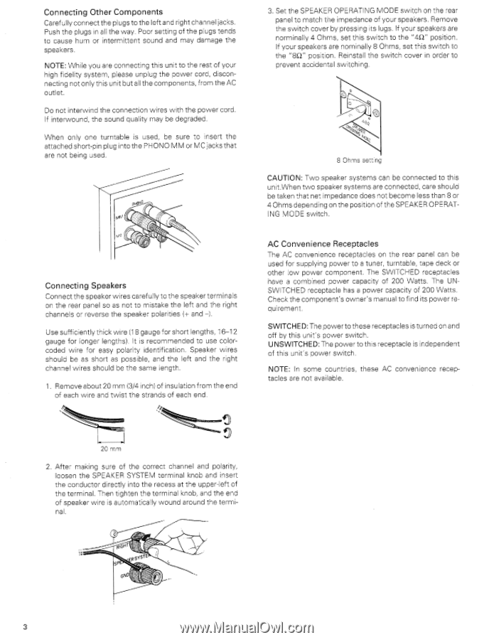
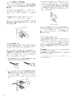
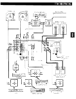
Connecting Other Components Carefully connect the plugs to the left and right channel jacks. Push the plugs in all the way. Poor setting of the plugs tends to cause hum or intermittent sound and may damage the speakers. NOTE: While you are connecting this unit to the rest of your high fidelity system, please unplug the power core, disconnecting not only this unit but all the components, from the AC outlet. Do not interwind the connection wires with the power cord. If interwound, the sound quality may be degraded. When only one turntable is used, be sure to insert the attached short-pin plug into the PHONO MM or MC jacks that are not being used. MM Connecting Speakers Connect the speaker wires carefully to the speaker terminals or the rear panel so as not to mistake the left and the right channels or reverse the speaker polarities (-r and -I. Use sufficiently thick wire (18 gauge for short lengths, 16-12 gauge for longer lengths). It is recommended to use colorcoded wire for easy polarity identification. Speaker wires should be as short as possible, and the left and the right channel wires should be the same length. 1 . Remove about 20 mm (3/4 inch) of insulation from the end of each wire and twist the strands of each end 3. Set the SPEAKER OPERATING MODE switch on the rear panel to match the impedance of your speakers. Remove the switch cover by pressing its lugs. If your speakers are norminally 4 Ohms, set this switch to the "4O" position. If your speakers are nominally 8 Ohms, set this switch to the "M" position. Reinstall the switch cover in order to prevent accidental switching. 8 Ohms setting CAUTION: Two speaker systems can be connected to this unit.When two speaker systems are connected, care should be taken that net impedance does not become less than 8 or 4 Ohms depending on the position of the SPEAKER OPERATING MODE switch. AC Convenience Receptacles The AC convenience receptacles on the rear panel can be used for supplying power to a tuner, turntable, tape deck or other low power component. The SWITCHED receptacles have a combined power capacity of 200 Watts. The UNSWITCHED receptacle has a power capacity of 200 Watts. Check the component's owner's manual to find its power requirement. SWITCHED: The power to these receptacles is turned on and off by this unit's power switch. UNSWITCHED: The power to this receptacle is independent of this unit's power switch. NOTE: In some countries, these AC convenience receptacles are not available. 2C mm 2. After making sure of the correct channel and polarity, loosen the SPEAKER SYSTEM terminal knob and insert the conductor directly into the recess at the upper-left of the terminal. Then tighten the terminal knob, and the end of speaker wire is automatically wound around the terminal. C sP ENO 3
-
 1
1 -
 2
2 -
 3
3 -
 4
4 -
 5
5 -
 6
6 -
 7
7 -
 8
8 -
 9
9 -
 10
10 -
11
-
12
 |
 |