Harman Kardon HK750 Owners Manual - Page 5
Harman Kardon HK750 Manual
 |
View all Harman Kardon HK750 manuals
Add to My Manuals
Save this manual to your list of manuals |
Page 5 highlights
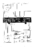
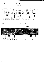
Connecting your tuner to the hk750 To connect a tuner, connect the left output connector of your tuner to the left TUNER INPUT (26) on your hk750. Similarly connect the right output connector of your tuner to the right TUNER INPUT on the hk750. Push the plugs in all the way so they are firmly seated, making good electrical contact. Connecting tape decks to the hk750 To connect a tape deck, connect the left output connector of your tape deck to the left TAPE 1 INPUT connector (28) on your hk750. Now connect the right output connector of your deck to the right TAPE 1 INPUT connector (28) on your hk750. Using a second pair of patch cords, connect the left input connector of your deck to the left TAPE 1 OUTPUT connector (29) on your hk750. Now connect the right input connector of your deck to the right TAPE 1 OUTPUT (29) on your hk750. Push the plugs in all the way so they are firmly seated, making good electrical contact. A second tape deck may be connected similarly using the TAPE 2 INPUT and OUTPUT connectors (30) (31). Connecting other equipment to the hk750 A pair of AUXILIARY INPUTS (27) is available at the rear of the hk750 for the connection of any "high level" output equipment. A special tuner for long wave, marine, aircraft or citizen's bands, etc., may be connected. Or you may choose to connect the output of the audio section of a television receiver. Any number of choices are available. Consult your audio dealer for information as to what equipment is compatible with your hk750. Connecting speakers Use two-conductor stranded wire to connect your speakers to the receiver. Eighteen gauge lamp cord (zip cord) is satisfactory, but a heavier gauge (16 or 14 gauge) is preferable, especially for distances over 25 feet. Cut two segements of wire long enough to reach each speaker. Separate the conductors at each end of the wire segments for a length of two or three inches. Then carefully remove about one- quarter inch of insulation from each free end. Twist the strands of each conductor so they are smooth and tight with no loose strands. Lamp cord usually provides a "code" that differentiates the two conductors. A conductor may be coded by a rib, sharp corner, or indentations molded along the length of the insulation. In some cases, a thin colored thread is molded along the length of the insulation. In others, one conductor is darker than the other, or the insulation of each conductor is of a different color. Connect the bare ends of one seg- ment of lamp cord to your right speaker as follows: Connect the coded conductor to the speaker's positive ("+") terminal, and the uncoded conductor to negative ("-"). (The "+" and "-" markings are in general use, although some speakers use other labeling systems, such as "1" and "2," "A' and "B" and so on.) Find the appropriate row of speaker connectors on the receiver marked SYSTEM 1 (32). Push in on the red plastic head of the connector marked RIGHT to reveal an opening beneath. Insert the bare end of the coded conductor into the opening. Release the connector. The conductor should now be locked firmly into place. Insert the uncoded conductor into the adjacent black connector marked GND. Repeat the procedure for the left speaker, taking care to observe the cod- ing of the conductors as described for the right speaker. If the code is followed as described, your speakers will be connected "in phase," which is important for solid bass and precise lateral location of the sound source. To connect a second pair of speakers, repeat the procedure for the right and left speakers of the second pair, using the receiver terminals marked SYSTEM 2 (33). 5
-
 1
1 -
 2
2 -
 3
3 -
 4
4 -
 5
5 -
 6
6 -
 7
7
 |
 |
