Harman Kardon HKTS 16 Owners Manual - Page 5
HKTS 210SUB Rear-Panel Connections - crossover frequency
 |
View all Harman Kardon HKTS 16 manuals
Add to My Manuals
Save this manual to your list of manuals |
Page 5 highlights
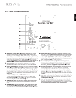
HKTS 9/16 HKTS 210SUB Rear-Panel Connections HKTS 210SUB Rear-Panel Connections ENGLISH 0 1 2 3 4 5 6 7 8 9 0. Phase switch: The Phase switch 0 determines whether the HKTS 210SUB's piston-like action moves in and out in phase with the satellite speakers. If the subwoofer were to play out of phase with the satellite speakers, the sound waves produced by the subwoofer could be canceled out, reducing bass performance and sonic impact. This phenomenon depends in part on the relative placement of all the speakers in the room. In most cases the Phase switch 0 should be left in the NORMAL position. However, it does no harm to experiment, and you can leave the Phase switch 0 in the position that maximizes bass response and impact. 1. Bass Boost switch: Set this switch to ON to enhance the HKTS 210SUB's low-frequency performance. Set this switch to OFF for normal low-frequency performance. 2. Power On Mode switch: If this switch is set in the AUTO position and the Power switch 8 is set to ON, the HKTS 210SUB will automatically turn itself on when it receives an audio signal and will enter the standby mode once no audio signal has been received for about 15 minutes. When this switch is set in the ON position, the HKTS 210SUB will remain on whether or not it is receiving an audio signal. An LED on the HKTS 210SUB's top panel indicates whether the subwoofer is in the on or standby state: • When the LED glows white, the HKTS 210SUB is turned on. • When the LED is not illuminated, the HKTS 210SUB is in standby mode. When the Power switch 8 is set to OFF, the LED will not be illuminated, no matter what setting the Power On Mode switch 2 is in. 3. Subwoofer Level control: Use this control to adjust the HKTS 210SUB's volume. Turn clockwise to increase the volume; turn counterclockwise to decrease the volume. 4. Input Mode switch: When this switch is in the "Normal" setting, the input signal from the Line-Level L/R In connectors 7 is active. When this switch is in the "LFE" setting, the input signal from the Line-Level LFE In connector 6 is active. 5. External Trigger input: Use the mini-plug of the supplied combination LFE and trigger cable to connect the External Trigger input to the trigger output of another compatible component. Whenever a trigger signal between 3V and 30V (AC or DC) is detected by the HKTS 210SUB, its amplifier will turn on. The HKTS 210SUB's amplifier will turn off after the trigger signal ceases. (This will occur even when the Power On Mode switch 2 is in the AUTO position.) 6. Line-Level LFE In connector: The signal from this connector bypasses the subwoofer's internal low-pass crossover. When you're connecting the subwoofer to the dedicated subwoofer output of a receiver/processor that has its own lowpass crossover network, use the Line-Level LFE In connector 6 and set the subwoofer's Input Mode switch 4 in the "LFE" position. 7. Line-Level L/R In connectors: The signals from these connectors pass through the subwoofer's internal low-pass crossover. When you're connecting the subwoofer to the preamp or subwoofer outputs of a receiver/processor that does not have its own low-pass crossover network, use both Line-Level L/R In connectors 7 and set the Input Mode switch 4 in the "Normal" position. If your receiver/processor has only one subwoofer output, you can use either the L or R connector. 8. Power switch: Set this switch in the ON position to turn the HKTS 210SUB on. The subwoofer will then either be on or in standby mode, depending on the setting of the Power On Mode switch 2. 9. Power cord (non-detachable): After you have made and verified all subwoofer and speaker connections described in this manual, plug this cord into an active, unswitched electrical outlet for proper operation of the HKTS 210SUB. DO NOT plug this cord into the accessory outlets found in some audio components. 5
-
 1
1 -
 2
2 -
 3
3 -
 4
4 -
 5
5 -
 6
6 -
 7
7 -
 8
8 -
 9
9 -
 10
10 -
 11
11 -
12
-
13
-
14
 |
 |
