Harman Kardon T12 Owners Manual - Page 2
Ventilation, Power, Requirements, Electrical, Connections, Antenna, Audio, Output, Operation,
 |
View all Harman Kardon T12 manuals
Add to My Manuals
Save this manual to your list of manuals |
Page 2 highlights
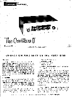
Ventilation: All electrical equipment generates heat which must be allowed to escape. Although the Overture II is well ventilated in itself, sufficient space should be allowed around it to permit free air flow. If it is placed in a bookcase, it should be located well toward the front, to provide as much clearance as possible at the rear. DO NOT place books or other objects on top of the Overture II. Covering the perforated metal cage will prevent proper air flow and will result in sharply reduced component and tube life. POWER REQUIREMENTS: Plug the AC power cord into any outlet furnishing 117 volts, 50 or 60 cycles house current. The exact voltage is relatively unimportant and may vary between 105 and 125 volts. Be sure, however, that you have a 50 or 60 cycle AC power source. If preferred, the AC line cord may be connected to the convenience outlet of your amplifier. ELECTRICAL CONNECTIONS AM Antenna: The Harman-Kardon ferrite loopstick built into the Overture II comprises all the antenna required for the finest in noise-free local AM reception. In locations more removed from metropolitan areas, an outdoor antenna may be required. This should consist of a single wire, as long as is reasonably practical. It should be kept away from large metal objects, power lines or electrical machinery. Connect one end of the outdoor antenna to the terminal marked "AM" on the Antenna Terminal Strip located at the rear of the chassis. FM Antenna: Due to the extremely high FM sensitivity of the Overture II, the 48" piece of wire furnished with the set will be sufficient antenna for all but the most difficult locations. One end of this wire should be fastened to the "FM" terminal of the Antenna Terminal Strip, the other end left free and extended as may be convenient. It may be tacked or stapled to the rear of the bookcase or equipment cabinet if necessary. If, for some reason, it is necessary to utilize other FM antenna types, we have listed for your convenience the following suggestions: 1. Special outdoor FM antennas may be used. These come in various types. For extremely difficult locations an in-line Yagi cut for the FM band or equivalent may be necessary. For reception of FM stations scattered in many directions, the non-directional antenna may be used. This non-directional type is. known as a double dipole and consists of two folded dipoles placed at right angles to each other. 2. Your present TV antenna may be used to obtain a maximum FM signal. A special antenna coupler or knife switch should be used when joining the FM line to the television antenna. AUDIO OUTPUT: Two jacks marked Audio Output will be found at the rear of the chassis. The two receptacles are connected in parallel. One of the Audio Output jacks should be connected to the amplifier tuner input receptacle with no more than a 3 foot length of shielded cable. The other jack may be connected to the input of a tape recorder. OPERATION In general, every control on a well designed, honestly considered high fidelity instrument has a specific useful function, related to each of the other controls.. Although this cannot be a treatise on the subject, an explanatory note on the relationship of the various front panel controls will doubtless prove useful in organizing and clarifying them for the user. Your Overture II incorporates the following operating controls located on the front panel. The Function Selector Switch (at the left) serves to turn the power off in its extreme counterclockwise position. In any other position, the power is turned on. This switch consecutively selects FM with AFC, FM without AFC and AM. The Tuning Knob (at the right) is used to tune for the desired station. Automatic Frequency Control: (AFC) FM broadcasting, by its very nature, eliminates almost all natural and man-made static. However, the characteristics of FM which makes this possible also causes problems in tuning. The Overture II incorporates a special electronic circuit known as Automatic Frequency Control that overcomes these problems and insures proper tuning even if the manual tuning is not accurately done. Therefore AFC always keeps the station in the center of the channel and eliminates distortion caused by inaccurate tuning. Tune across the FM scale with the Function Switch in the FM-AFC position. Note how the stations "pop" into place. Now tune to any station, preferably one with a musical program. Defeat the AFC by turning the Function Switch to the FM position, and tune slowly through the station from left to right. Notice that there are three points where the station sounds clean, interspersed with points of distorted sound. The middle clean-sounding point is the proper tuning position for the best tone quality with minimum noise and interference. Detune the station so that the sound is distorted. Turn the Function Switch to FM-AFC, and notice how the sound clears up. Actually, the tuning has been readjusted by the operation of the AFC circuit, which automatically retunes the electronic circuits to the center of the station channel. In order to take maximum advantage of the benefits of AFC, it is suggested that fine tuning be done with the function switch in the. FM position. When the switch is then turned to the FM-AFC position the AFC will improve this careful tuning by a factor of 10 to 1. This
-
 1
1 -
 2
2 -
 3
3 -
 4
4
 |
 |
