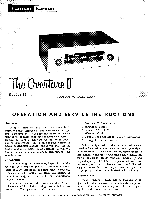
Harman Kardon T12 Owners Manual - Page 3
repairman.
 |
View all Harman Kardon T12 manuals
Add to My Manuals
Save this manual to your list of manuals |
Page 3 highlights
procedure is especially recommended in those cases where a weak station is found close to a stronger one. Under these conditions, the AFC may tend to reach for the strong station, and completely skip over the weak station. If the weak station is tuned with the AFC defeated, the AFC will lock it in, after it has been reinserted. NOTE: Volume and tone adjustment of the program source must be made at the amplifier. MAINTENANCE AND REPAIR In some installations, hum may be encountered due to a voltage difference between the amplifier, tuner and record changer chassis. This may be eliminated by reversing one or all of the AC power plugs. Simply reverse one at a time until improvement is experienced. Due to the conservative design and high quality components of the Overture II, no routine maintenance other than yearly tube-testing is required. Should trouble develop, however, only the most qualified serviceman should be employed, as special equipment and training is required to properly service high fidelity equipment. When changing tubes or performing repairs it is necessary to remove the cage and the safety interlock power cord. Do not use a "cheater" cord when the cage is removed as dangerous voltages will then be exposed. This instruction booklet contains diagrams and other information needed by your repairman. It should be kept available for his use. WARRANTY We warrant each Overture II, Model T-12 to be free from defects in material and workmanship under normal use and service, and in accordance with the conditions herein below set forth, for a period of 1 year from date of delivery to the original purchaser, and agree to replace or repair any part or parts, with the exception of tubes which are under the manufacturer's 90 day warranty, returned to us within said 1 year, with transportation prepaid, and which our examination shall disclose to our satisfaction to have been thus defective. This warranty does not include free labor, nor is it applicable to any instrument which shall have been repaired or altered in any way so as in our judgment to affect its stability or reliability nor which has been subject to neglect, misuse, abuse, negligence or accident nor which has had the serial number altered, effaced, or removed. Neither shall this warranty apply to any instrument which has been connected otherwise than in accordance with the instruction furnished by us. This warranty is expressly in lieu of all other warranties, express or implied, and of all other obligations or liabilities on our part, and we neither assume nor authorize any representative or other person to assume for us any other liability in connection with the sale of the Model T-12, Overture II. SERVICE NOTES Servicing printed circuits is a simple matter and is no more complicated than servicing conventionally wired circuits. Printed circuit receivers, can be more easily repaired, if certain precautions are observed. Standard components are used throughout and can be removed and replaced by any serviceman. No special tools or skills are necessary. However, some parts which have special mounting and connection lugs should be replaced with exact duplicate parts. Avoid Damage to Copper Foil Be careful when removing components from the board. However, if the copper foil wiring is damaged a piece of wire can be used to replace the damaged foil. Small breaks can be "jumped" with molten solder. Larger breaks can be repaired with ordinary hook up wire. It is unnecessary to replace the entire board because of foil breakage. Avoid Damage to Printed Circuit Board Do not apply excessive pressure to the printed circuit board or components. This is especially important to note when changing tubes. Although the board is sturdy in construction and mounting, it may crack or break if proper care is not taken when servicing. In case the board is to be removed from the chassis, remove the mounting screws around the edges and unsolder the few leads that connect between the board and the chassis. If this is done, a vise with protected jaws should be used to hold the board while servicing and care should be taken not to exert excessive pressure against the board. Avoid Excessive Deposits of Solder In some areas on the printed circuit board, the wiring is very closely spaced. When resoldering a new component avoid excessive deposits of solder. Excessive solder may cause a short or an intermittent trouble to occur later which may be difficult to locate. Avoid Overheating When using the soldering iron (35 watts or less), do not overheat the component terminals or the copper foil. Excessive heat (applying soldering iron longer than necessary, using a higher wattage soldering iron than recommended, or using a solder gun) may cause the bond between the board and foil to break. This will necessitate replacement or repair of the foil connection. Tools and Materials Required (1) Low wattage soldering iron with a small point or wedge (rating should not exceed 35 watts). (2) Small wire brush. (3) 60% tin, 40% lead, low temperature rosin core solder. (4) Thin bladed knife. (5) Small wire pick, or soldering aid. REPLACING COMPONENTS Soldering Replacement Component to Old Leads Cut the leads where they enter the defective component. Clean off the ends of the leads, leaving as much of the leads as possible. Make a small loop in each lead of the replacement component and slide the loops over the remaining leads of the old component. Caution should be taken not to overheat the connection since the copper foil may peel or the original component lead may
-
 1
1 -
 2
2 -
 3
3 -
 4
4
 |
 |
