Harman Kardon T12 Owners Manual - Page 4
kardon
 |
View all Harman Kardon T12 manuals
Add to My Manuals
Save this manual to your list of manuals |
Page 4 highlights
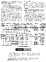
_i'out of the board. This is possible due to heat transfer through the leads. The lead length of the replacement part should be kept reasonably short to provide some mechanical rigidity. Unsoldering and Resoldering Components To test a component or if the component is mounted in such a manner that the above method can not be used (such as vertically mounted capacitors, etc.) the component can be replaced by unsoldering it. This procedure should be used whenever it is necessary to unsolder any connections to replace defective components. (a) Heat the connection on the wiring side of the board with a small soldering iron. When the solder melts, brush away the solder. Do not overheat the connection. In the process of removing the solder, caution must be taken to prevent excessive heating. Therefore, do not leave the iron on the connection while brushing away the solder. Melt the solder, remove the iron and quickly brush away the solder. It may require more than one heating and brushing process to com- pletely remove the solder. (b) Insert a knife blade between the wiring foil and the "bent-over" component lead and bend the lead perpendicular to the board. (It may be necessary to apply the soldering iron to the connection while performing this step as it is sometimes difficult to completely break the connection by brushing.) Do not overheat the connection. (c) While applying the soldering iron to the connections, "wiggle" the component until it is removed. (d) Remove any small particles of solder using a clean cloth dipped in solvent. (e) A thin film of solder may remain over the hole through the board after removing the component. Pierce the film with the lead from the new component after heating the solder film with the soldering iron. (f) Insert the leads of the new component through the holes provided. Cut to desired length and bend over the ends against the copper foil. Resolder the connection with 60/40 low temperature solder. FUNCTION SIGNAL GENERATOR SIGNAL SWITCH INPUT SETTING FREQ. MOD. POINT AM 455 KC 30% AM AM RF GANG AM 1500 KC 30% AM AM ANT. TERM. AM 600 KC 30% AM AM ANT. TERM. AM 1500 KC OUTPUT CONNECT DIAL INDICATOR INDICATOR SETTING TO: AC-VTVM TUNER 1600 KC OR SCOPE OUTPUT AC-VTVM TUNER 1500 KC OR SCOPE OUTPUT AC-VTVM TUNER 600 KC OR SCOPE OUTPUT REPEAT STEP 2 ADJUST 2 AM IF TRANS. OSC & ANT TRIMMERS OSC COIL & LOOPSTICK OUTPUT INDICATION MAXIMUM OUTPUT MAXIMUM OUTPUT MAXIMUM OUTPUT AM ALIGNMENT PROCEDURE FUNCTION SIGNAL GENERATOR SIGNAL OUTPUT CONNECT DIAL ADJUST OUTPUT SWITCH INPUT INDICATOR INDICATOR SETTING INDICATION SETTING FREQ. FM 10.7 MC MOD. POINT 300KC FM FM MIXER AC-VTVM 60 CPS GANG OR SCOPE TO: TEST POINT 3 FM IF TRANS. MAX GAIN & SYMMETRY FM 10.7 MC 300KC FM FM MIXER AC-VTVM TUNER 60 CPS GANG OR SCOPE OUTPUT DISCR. TRANS. S PATTERN OF MAX GAIN & SYMM. FM 106 MC 300KC FM FM ANT. AC-VTVM TEST 106 MC 106 MC OSC MAXIMUM 60 CPS" TERMINAL OR SCOPE POINT RF, MIXER OUTPUT TRIMMERS FM 90 MC 300KC FM FM ANT. AC-VTVM TEST 90 MC OSC, ,RF, MAXIMUM 60 CPS TERMINAL OR SCOPE POINT MIXER COILS OUTPUT FM ALIGNMENT PROCEDURE harman kardon Harman-Kardon high fidelity instruments incorporate advanced production techniques as well as advanced circuit features. They reflect the highest state of the art of fine audio equipment. We hope your unit provides you with many hours of listening enjoyment. Our Customer Service Department is maintained to answer your correspondence about High Fidelity and to make recommendation of appropriate companion accessories. Please feel free to write without obligation.
-
 1
1 -
 2
2 -
 3
3 -
 4
4
 |
 |
