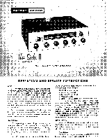
Harman Kardon TA12 Owners Manual - Page 3
Speaker, Connections, Connecting, loudspeaker, CAUTION, loudspeakers, OPERATION, TECHNICAL,
 |
View all Harman Kardon TA12 manuals
Add to My Manuals
Save this manual to your list of manuals |
Page 3 highlights
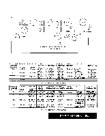
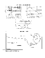
Speaker Connections: A unique method of connecting one or two loudspeakers is incorporated in the Solo II in order that you may derive maximum enjoyment from this superlative instrument with any of today's fine speaker systems. Connecting one loudspeaker: Connect one of the two speaker leads to terminal "G" and the other lead to "A" on the three screw terminal strip at the rear of the chassis marked "SPEAKER." For speakers with an impedance of 12 to 24 ohms place the Impedance Selector Jumper located at the rear of the chassis so that the center terminal is connected to the terminal marked 16. For speakers with an impedance of 4 to 12 ohms place the Impedance Selector Jumper so that the center terminal is connected to the terminal marked 8. The front panel Speaker Selector Switch should then be placed in the "A" position. CAUTION: A jumper is connected between "A" and "B" terminals on the Speaker Terminal Strip on the rear of this instrument. When only one loudspeaker is used, this jumper must be connected at all times. It should be removed only when two separate speakers are connected. This precaution will prevent the set from appearing to be inoperative when only one speaker is connected, and the Speaker Selector Switch is improperly set. Connecting two loudspeakers: If you wish to operate two loudspeakers with the Solo II and use either one or both together, connect the second speaker to terminals "G" and "B" on the Speaker Terminal Strip. For best operation, both speakers should have the same impedance, although a slight mismatch will not disturb the overall response. To select speaker A, place the front panel Speaker Selector.Switch in the "A" position. To select speaker B, place the switch in position "B". To activate both speakers simultaneously, place the front panel Speaker Selector Switch in position marked "AB". OPERATION In general, every control on a well designed, honestly considered high fidelity instrument has a specific useful function, related to each of the other controls. Although this cannot be a treatise on the subject, an explanatory note on the relationship of the various front panel controls will doubtless prove useful in organizing and clarifying them for the user. Your Solo II incorporates the following operating controls located on the front panel. Viewing the instrument from the front and reading from left to right you will note the Scratch Filter Control, Bass Control, Treble Control, Loudness (volume) Control (on/off switch is incorporated into this control), Dynamic Con- tour Control and Tuning Control. In the upper left hand corner you will find the Function Selector Switch and in the upper right corner the Speaker Selector Control. To operate, turn the Function Selector Switch to the AM position. Set the Bass and Treble tone controls so that the white lines on the knobs point straight up. This will assure a "flat" uncompensated response. Turn the set on by rotating the Loudness Control in a clockwise position; now set this Loudness Control at 1/3 volume. The Contour Control should remain on zero at this time. Tune for an AM station. Once the desired program is located and tuned in, adjust the volume so that the music is played at a comfortable level. Now adjust the Bass and Treble tone controls to correct for the electro-acoustic characteristics of the loudspeaker you are using and the acoustic characteristics of the room in which you are listening. Modify each control until settings are chosen which in your total system create the proper sense of aural balance and evenness. Now reduce the Loudness (Volume) control setting somewhat lower than normal listening level in your room. You will note that the full bodied lifelike quality you experienced at high listening level has disappeared (this because of the Fletcher-Munson effect described in the paragraph on the H/K Dynamic Loudness Contour). With all other controls unchanged, select the best contour setting for you. Do this by switching quickly through the several positions until you find the one which most nearly duplicates the full bodied sound you enjoyed at high level. Now turn the Loudness control up to the level at which you wish to listen (perhaps the maximum level you can permit in your home). You'll find that there is automatic compensation of contour wherever you set the Loudness control thereafter. In fact, under normal circumstances you should not find it necessary to readjust the tone controls or the contour selector once having chosen the correct settings for you, your room and your system. TECHNICAL EXPLANATION OF THE CONTROLS The Function Selector Switch has 8 positions: AUX, AM, FM, FM-AFC, RIAA-Rumble, RIAA, LP and EUR. Its use is to select the desired type of program. Listed below is the explanation of the various functions. Automatic Frequency Control: (AFC) FM broadcasting, by its very nature, eliminates almost all natural and man-made static. However, the characteristics of FM which makes this possible also causes problems in tuning. The Solo II incorporates a special electronic circuit known as Automatic Frequency Control that overcomes these problems and insures proper tuning even if the manual tuning is not accurately 3
-
 1
1 -
 2
2 -
 3
3 -
 4
4 -
 5
5 -
 6
6 -
 7
7 -
 8
8 -
 9
9 -
10
 |
 |
