Harman Kardon TA12 Owners Manual - Page 8
characteristics
 |
View all Harman Kardon TA12 manuals
Add to My Manuals
Save this manual to your list of manuals |
Page 8 highlights
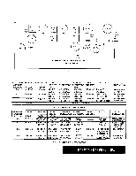
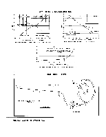
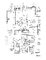
EZ81 (V1) B+ 330V RECTIFIER 3 8 100 mfd 40 mfd 20 mfd EL84 (V5) OUTPUT PRIMARYOUTPUT TRANSFORMER EL84 (V6) OUTPUT a + 310V ECC-83 (V2) PREAMPLIFIER B + 250V h. • 0 04 14 4.• VOLUME CONTROL 10 mfd B +250V TR BLE CONTROL 6AU6 (V3) VOLTAGE AMPLIFIER BASS CONTROL 6C4 (V4) PHASE INVERTER V6 ECC85 V1 ECCB5 T2 V2 6BA6 T3 OSC INJECTION TEST POINT FEEDBACK V3 6AU6 These photographs show the printed circuit boards used in the Harman-Kardon Solo II and indicate to some degree the corn-, plexity of design and painstak-' ing care required in the plan- ning of such a unit. FM frequencies, by their very nature, require careful placement of parts and leads. In conventional point to point wir- ing, misplacement of a wire, even a slight amount from its correct position will adversely affect operation. The amplifier has been de- signed to use printed circuits in those areas where each component and each connecting lead must be carefully positioned in order to afford best possible operation. This design form results, we feel, in providing the best possible characteristics and reflects the highest state of the art in the construction of fine high fidelity equipment. T4 V4 6AU6 LIMITER TEST POINT • fi () ) '0 11.4A4 0 x'71 4 :• • O- 77%4.' ..:•-• + TEST POINT T7 V7 6BE6 ELECTROLYTIC CAPACITOR T6 AM OUTPUT T5 V5 6AL5 DISCR. TEST POINT
-
 1
1 -
2
-
 3
3 -
 4
4 -
 5
5 -
 6
6 -
 7
7 -
 8
8 -
 9
9 -
 10
10
 |
 |
