Hayward Aqua Rite AQ-RT-PRO prior to Oct 08 - Page 18
Wiring, Input Power - t cell 15
 |
View all Hayward Aqua Rite manuals
Add to My Manuals
Save this manual to your list of manuals |
Page 18 highlights
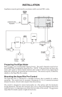
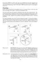
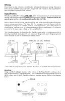
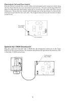
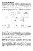
Wiring Power must be shut off at the circuit breaker before performing any wiring. Be sure to follow Local and NEC electrical codes. To provide safe operation, the Aqua Rite Pro must be properly grounded and bonded. Input Power: Wire the Aqua Rite Pro to the LOAD SIDE of the filter pump timer. It is very important that the Aqua Rite Pro is powered only when the pump is running. Note that this circuit must be protected by a Ground Fault Circuit Breaker (GFCB). Refer to the wiring label on the Aqua Rite Pro as well as the diagram below to determine correct wiring connections. The Aqua Rite Pro is shipped from the factory with the configuration jumpers in 240VAC position. If using 120VAC, move the jumpers as shown below. IMPORTANT: If a dispensing device will be used (page 17), it must be powered by the same input voltage as the Aqua Rite Pro. For Canadian models, the Aqua Rite Pro shall be connected to a circuit protected by a class A ground fault interrupter. Be sure to connect the ground wire to the green ground screw terminal located on the bottom of the enclosure. 120 VAC AQUA RITE Pro TYPICAL 240 VAC WIRING AQUA RITE Pro TIMECLOCK SUBPANEL PCB PCB BONDING LUG LOAD GND LINE GROUND IMPORTANT: MOVE JUMPERS TO POSITIONS SHOWN BONDING LOOP PUMP Note: Wire the pump directly to the timeclock--do not use the Aqua Rite Pro as a junction box. Bonding: A lug used for bonding is attached to the bottom of the Aqua Rite Pro enclosure (two lugs are provided for Canadian models). The Aqua Rite Pro must be bonded with an 8 AWG copper wire (6 AWG Canada) to the pool bonding system. Refer to the diagram below. Cutout for cell cable Bottom of Aqua Rite Pro Enclosure Second bonding lug for Canadian models only 15 Bonding lug to pool bonding system
-
 1
1 -
2
-
3
-
4
-
5
-
6
-
7
-
8
-
9
-
10
-
11
-
12
-
 13
13 -
 14
14 -
 15
15 -
 16
16 -
 17
17 -
 18
18 -
 19
19 -
 20
20 -
 21
21 -
 22
22 -
 23
23 -
24
 |
 |
