Hayward C100S SwimClear Single Element Manual - Page 5
Caution - c100 filter cartridge replacement
 |
View all Hayward C100S manuals
Add to My Manuals
Save this manual to your list of manuals |
Page 5 highlights
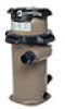
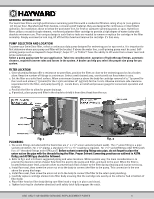
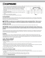
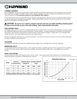
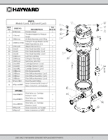
8. A 1 ½" NPT filter drain plug is furnished with each filter. When making threaded connections to the filter use plastic adapters. Apply three turns of PTFE tape (or use special plastic pipe sealant) to male threads. Screw the fitting into the thread hand tight; REQUIRED CLEARANCE then using a strap wrench, tighten one more full turn. Additional tightening is unnecessary and could result in broken or damaged valve body. SIDE IN CM ABOVE IN CM 9. A manual air relief valve is furnished to aid in bleeding off unwanted C100S 18 45 12 30 air when starting the filter. 10. All electrical connections should be made in accordance with local C150S 18 45 15 38 codes. C200S 18 45 18 45 11. Check for joint leaks before operating. 12. Refer to pump instruction booklet for pump information. Fig. 3 FILTER MOUNTING Secure filter to level concrete slab or other rigid surface to meet all local and national codes. Use fasteners appropriate for the material of the surface being fastened to. Use 2 of the 4 available mounting holes (see fig.1) on opposite corners of the filter base to ensure the filter is secure and level. CAUTION: Be careful not to over tighten the fasteners when mounting the filter. Failure to do so may cause the base of the filter to crack at the mounting locations causing the filter to be unstable. STARTING THE FILTER Be sure filter drain is closed. Open manual air relief valve and open the suction and return valves (when used). CAUTION: All suction and discharge valves must be open when starting the system. Failure to do so could cause severe personal injury and/or property damage. Be sure lock ring is locked and in latched position. Stand clear of the filter. Prime and start the pump, following the manufacturer's instructions. Air trapped in the system will automatically vent to the pool and out the manual air relief valve. Close the air relief valve when a steady stream of water (not air or air and water) is being discharged. FILTERING Filtration starts as soon as flow is steady through the filter. As the filter cartridge removes dirt from the pool water, the accumulated dirt causes a resistance to flow. As a result, the gauge pressure will increase and flow will decrease. When the indicated pressure increases 7 to 10 psi (0.49 to 0.70 Bar) above the starting pressure, or when flow decreases below the desired filtration rate, clean or replace the filter cartridge. CLEAN / REPLACE CARTRIDGE REMOVING CARTRIDGE ELEMENT 1. Shut off the pump. 2. If filter is located below water level, close valves or block off suction & discharge lines to prevent backflow of water from the pool. 3. Remove drain plug and open the manual air relief valve to allow water to drain from filter. 4. Depress safety latch and unscrew the lock ring (counterclockwise direction). Carefully lift off filter head with the attached lock ring to gain access to filter cartridge. (Set Head on a flat surface on top of the handle) 5. Lift out cartridge and clean or, replace with a clean, spare cartridge. (See Cleaning Cartridge.) 6. Clean body o-ring in filter head. REINSTALLING CARTRIDGE ELEMENT 1. Clean any collected debris from the bottom of filter body. Clean the Body o-ring seal area. 2. Carefully replace cartridge element into filter body ensuring that the cartridge sits evenly on the collector hub in bottom of filter body. 3. Place filter head on filter body (being sure filter head 0-ring is in place and clean). 4. Tighten lock ring (in clockwise direction) until safety latch fully engages the catch. 5. Proceed as in STARTING THE FILTER. USE ONLY HAYWARD GENUINE REPLACEMENT PARTS 5
-
 1
1 -
 2
2 -
 3
3 -
 4
4 -
 5
5 -
 6
6 -
 7
7 -
 8
8
 |
 |