Hayward Chlorine Model: ALL MODELS - Page 4
Uinstallation - feeders
 |
View all Hayward Chlorine manuals
Add to My Manuals
Save this manual to your list of manuals |
Page 4 highlights
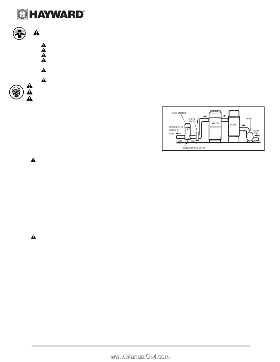
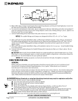
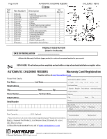
DANGER Mixing Chemicals or using fast dissolving chemicals may result in explosion and/or fire. To avoid death, serious injury or major property damage: Use only slow dissolving Trichlor Chlorine tablets. Never use fast dissolving Trichlor Chlorine tablets. Never mix chemicals. Never mix Trichlor Chlorine tablets with Calcium Hypochlorite, or with any other form of concentrated chlorine or other chemicals. Fire and/or explosion may result. Never add any other types of chlorine, pH adjusters, shock treatments or algaecides through the skimmer. If these products must be used, they should be added directly into the pool water. Never isolate chlorine feeder with valves or other devices. WARNING Wear eye and skin protection while maintaining or servicing this unit. WARNING Do not inhale fumes from the chlorinator or chemical container. WARNING Chlorine feeder may be under pressure. Use caution removing cover. INSTALLATION: CL-100/200 1. Your CL-100/200 automatic chlorine feeder is designed for permanent installation in the pool water return line. 2. Always install the chlorine feeder after the heater. If there is no heater, install after the filter. CAUTION Damage to the heater or filter may result if concentrated chlorine is allowed to flow through them. An in-line positive seal corrosion resistant check valve should be installed to reduce backflow of chlorine gas when the system is shut off. If the chlorine feeder is located below water level, you may want to install a check valve to prevent water backflow when operating/servicing the unit. The CL100 has this feature built in. 3. Both the CL-100/200 are furnished with 1 1/2" female threads. If PVC socket (solvent weld) connections are desired, order SP1500UNPAK2, socket flush union end connectors package. For threaded male and union connectors, order SP1500UNMPAK1 male union connector package (two required). Thread or socket adapters may also be used. Only use pipe sealants formulated and approved for use with ABS plastic connections (e.g. Teflon Tape, Permatex Form-A-Gasket No. 2, Laco Plasto-Joint stick). Do not over tighten pipe fitting. Proper fitting makeup is hand tight plus 1 to 1 1 /2 turns maximum. NOTICE: After starting up system, re-check all connections for leaks. Re-tighten as required. CAUTION Never install chlorine feeder directly into copper plumbing as pipe damage may occur. If you have brass or bronze backwash valves, or other sensitive metallic components, consult your dealer for precautions or recommendations for your particular system. CL-110/220 1. The inlet connection should be made in the piping after the pump and before the filter. Mark location on pipe. 2. The outlet connection should be made in the piping after the heater. If no heater is being used, connection should be made after the filter. Mark location on pipe. 3. Based on the locations from steps. No. 1 and No. 2, cut tubing to required lengths. Be sure ends are cut evenly and cleanly. 4. Wrap Teflon tape on larger male thread of Check Valve and thread it hand tight plus ½ turn into outlet port of chlorinator. DO NOT OVER TIGHTEN. NOTICE: The Check Valve is marked with a "dot". It also has a ball that "clicks" when you shake it. Page 4 of 8 USE ONLY GENUINE HAYWARD PARTS AUTOMATIC CHLORINE FEEDERS ISCLSERIES REV B
-
 1
1 -
 2
2 -
 3
3 -
 4
4 -
 5
5 -
 6
6 -
 7
7 -
 8
8
 |
 |