Hayward HeatPro Heat Pro Installation - Page 17
Connecting to Remote Systems, Initial Start-Up, Note: Damage caused by flow rates outside this range - heater parts
 |
View all Hayward HeatPro manuals
Add to My Manuals
Save this manual to your list of manuals |
Page 17 highlights
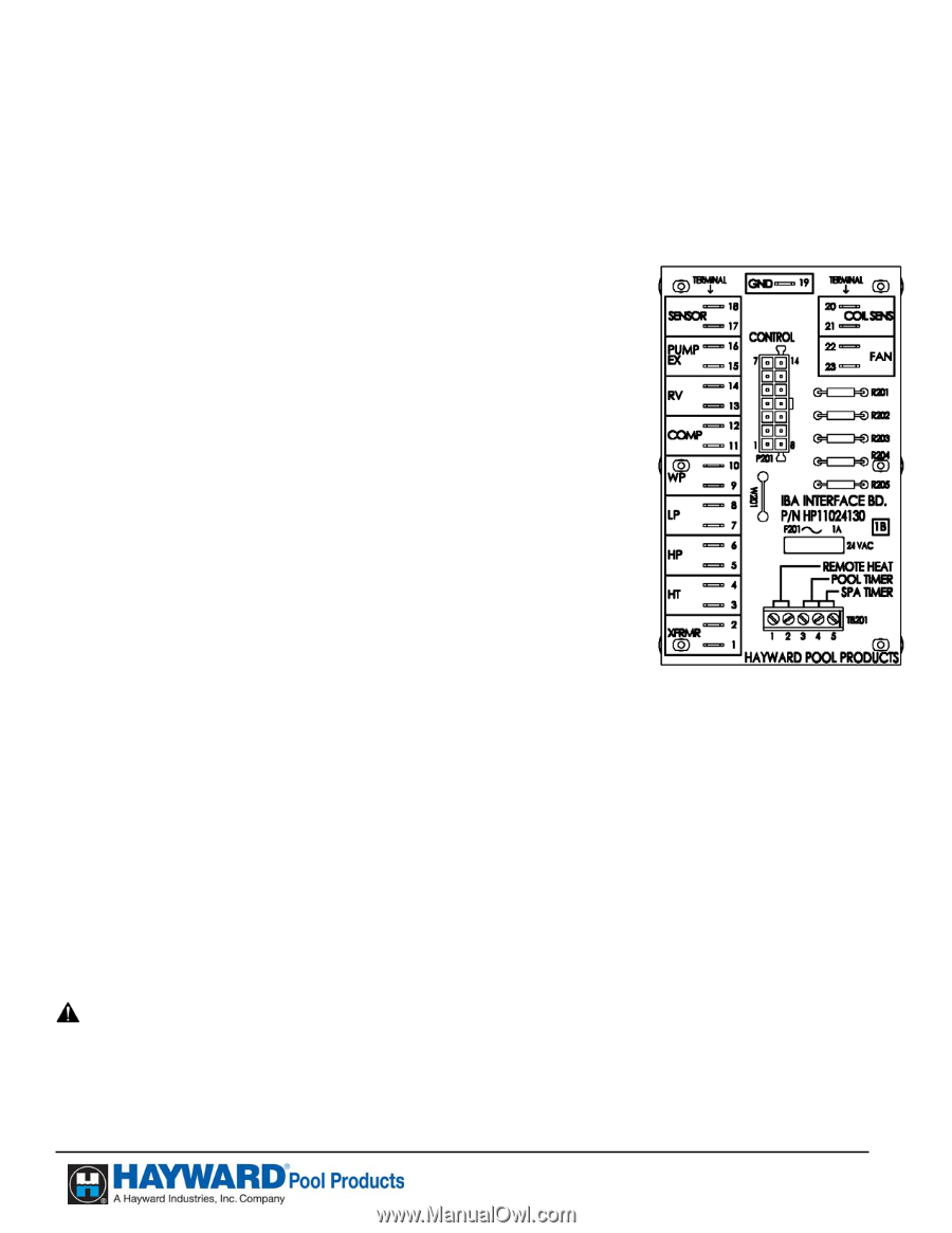
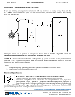
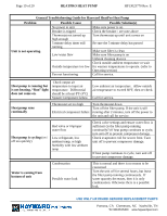
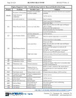
Page 17 of 20 HEATPRO HEAT PUMP HP13023770 Rev: E Connecting to Remote Systems HAYWARD heat pumps are compatible, in the heating mode only, with one or more of the remote systems in the pool and spa industry today. Thoroughly read all installation instructions of the remote system before connecting this unit. The figure below shows the remote systems connections to the HAYWARD heat pump. Connection to Compatible Remote Systems: • Connect two wires (24 VAC) from the remote system. In the TB201 Terminal Block of the Interface board, connect one wire into terminal 1, and the other into terminal 2. • The thermostat on the heat pump must be in the "Standby" mode for the remote system to control the unit. Or • Connect three wires marked as pool, spa, and common from the remote system to TB201 Terminal Block as follows: Terminal 3 = Pool Terminal 4 = Common Terminal 5 = Spa • The thermostat on the heat pump must be in the "Standby" mode for the remote system to control the unit. Thermostat Interface Board in the unit Control Box • The thermostat on the heat pump will control the water temperature. Initial Start-Up After completing the electrical and piping connections to the pool heater, follow the procedures outlined below to ensure that the pool heater is functioning properly. Before proceeding, MAKE CERTAIN there are no air or water leaks in any plumbing connections or piping and water flow is within the proper flow rate ranges. The proper flow rate ranges for ALL Hayward HeatPro Heat Pumps are a minimum of 30 GPM and a maximum of 75 GPM. Note: Damage caused by flow rates outside this range will void the warranty. CAUTION - Keep all objects off the top of the heat pump. Blocking airflow could damage the unit and will void the warranty. USE ONLY HAYWARD GENUINE REPLACEMENT PARTS Pomona, CA Clemmons, NC Nashville, TN Tel: 908.351.5400 www.haywardpool.com
-
 1
1 -
2
-
3
-
4
-
5
-
6
-
7
-
8
-
9
-
10
-
11
-
 12
12 -
 13
13 -
 14
14 -
 15
15 -
 16
16 -
 17
17 -
 18
18 -
 19
19 -
 20
20 -
 21
21
 |
 |