Hayward Power-Flo Model: ALL - Page 8
Shaft Seal Change Instructions cont., Troubleshooting - pump parts
 |
View all Hayward Power-Flo manuals
Add to My Manuals
Save this manual to your list of manuals |
Page 8 highlights
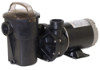
Power-Flo LX™ / Power-Flo II™ Pump Series Shaft Seal Change Instructions (cont.) Exercise extreme care in handling both the rotating and the stationary sections of the two-part replacement seal. Foreign matter or improper handling will easily scratch the graphite and ceramic sealing surfaces. 1. Shut off water flow to pump by closing appropriate valves or by plugging both the skimmer outlet port and return port to pool. Disconnect piping or hoses from the motor/pump assembly. 2. Remove the strainer by disengaging and removing the strainer cover. Remove the basket. Lift up on strainer 'C' clip and remove. Finally, slide strainer housing forward and remove. 3. Unscrew eight (8) screws and remove pump cover, exposing the impeller. 4. Remove the canopy or the shaft cover plate from the end of motor opposite the impeller. 5. Hold the motor shaft securely by either inserting a screwdriver in slot at end of shaft or by using an open-end wrench to engage the flat surfaces provided near end of motor shaft. Rotate the impeller ina a counterclockwise direction and remove it from the motor shaft. 6. Note how the steel spring section of the old seal is positioned on impeller hub and remove it by pulling from the impeller. 7. Loosen four (4) motor through bolts from the back of motor and remove pump housing/shroud from the front of the motor. 8. Remove the ceramic stationary portion of the old seal by pressing the white ceramic seat out of the pump housing recess. If assembly is tight, tap lightly from the "motor" side. 9. Clean and lubricate the impeller stem and the pump housing recess with a dilute solution of non-granulated liquid-type soap. Do not use petroleum or silicone lubricants as these can contribute to seal leakage. 10. Press the new rotating portion of the seal assembly onto the impeller stem with the polished black graphite surface facing away from the impeller. 11. Carefully press the stationary ceramic portion of the seal into the recess of the pump housing/shroud, with the polished flat surface facing out. 12. Carefully insert the motor shaft through the pump housing/shroud and align with white ceramic stationary seal assembly in place and secure the motor to pump housing/shroud with four (4) motor through bolts removed in step #7. Be sure motor base and pump discharge port are positioned properly. Alternately tighten the motor through bolts until the pump housing is secure. Make certain motor shaft turns freely before proceeding. 13. Screw the impeller (clockwise) with the rotating portion of seal in place onto the motor shaft. Hand-tighten the impeller in place. 14. Clean (replace if necessary) the O-ring and replace on pump cover. Assemble the pump cover to the pump housing/ shroud with the eight (8) screws removed in step #3. Tighten screws alternately and evenly. 15. Re-assemble strainer by sliding strainer housing onto pump cover. Install strainer 'C' clip by pushing clip down onto grooved pump cover coupling. Insert basket and fasten strainer cover. 16. Reconnect pump to the piping or hoses provided. Open all valves and make sure that the pump strainer housing is full of water before restarting the pump. Troubleshooting Motor Will NOT Start - Check For: 1. Improper or loose wiring connections; open switches or relays; tripped circuit breakers, GFCI's, or blown fuses. 2. Manually check rotation of motor shaft for free movement and lack of obstruction. (See steps 4 & 5 of "Shaft Seal Change Instructions" in this manual.) 3. If you have a timer, be certain it is working properly. Bypass it if necessary. Motor Shuts OFF - Check For: 1. Undersized wiring; loose connections; etc. 2. Low voltage at motor or power drop (frequently caused by undersized wiring or extension cord use). 3. Mechanical binding and electrical overload. NOTE: Your Hayward pump motor is equipped with an "automatic thermal overload protector." The motor will automatically shut off if power supply drops before heat damage can build up causing windings to burn out. The "thermal overload protector" will allow the motor to automatically restart once the motor has cooled, provided the power source is again up to proper levels. It will continue to cut On/Off until the problem is corrected. Be sure to correct cause of overheating.
-
 1
1 -
2
-
 3
3 -
 4
4 -
 5
5 -
 6
6 -
 7
7 -
 8
8 -
 9
9 -
 10
10 -
 11
11 -
 12
12
 |
 |
