Hayward Salt & Swim ABG 23 000 gallons outlet plug has straight blades Salt &a - Page 5
Mounting the Salt & Swim 3C Control Box, Plumbing
 |
View all Hayward Salt & Swim ABG 23 000 gallons outlet plug has straight blades manuals
Add to My Manuals
Save this manual to your list of manuals |
Page 5 highlights
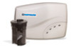
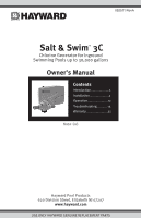
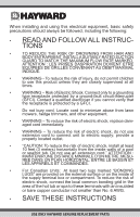
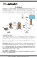
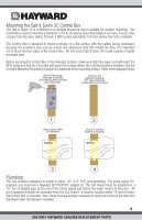
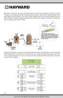
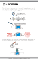
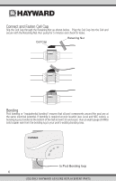
Mounting the Salt & Swim 3C Control Box The Salt & Swim 3C is contained in a raintight enclosure that is suitable for outdoor mounting. The Control Box must be mounted a minimum of 10 ft. (4 meters) horizontal distance (or more, if local codes require) from the pool, within 3ft from a GFCI outlet, and within 15ft from where the Cell is installed. The Control Box is designed to mount vertically on a flat surface with the cables facing downward. Because the enclosure also acts as a heat sink (disperses heat from inside the box), it is important not to block the four sides of the Control Box. Do not mount Salt & Swim 3C inside a panel or tightly enclosed area. Before securing the Control Box to the intended location, make sure that the power cord will reach the GFCI outlet and that the Cell cable will reach the location where the Cell Vessel will be installed. Use the included Mounting Template to position the fasteners to the mounting surface. Refer to the diagram below. Secure Mounting Template to desired mounting location and drill mounting holes. Screw in top fasteners leaving 1/8" space between screw head and surface Use to mount on flat surface Use to mount on post MOUNTING TEMPLATE Use the included hardware or your own hardware (suitable for a 20lb load) to mount the Control Box to a wall or post within 3 feet of a GFCI outlet, making sure that the cord will reach. Use this template to locate and drill fastener holes. After marking the mounting surface with this template, screw in top fasteners leaving 1/8" space between screw head and surface Hang Control Box on fasteners Screw in bottom fasteners securely Use to mount on flat surface Use to mount on post 092xxx 1 Hang Control Box on fasteners 2 Screw in bottom fasteners securely. 3 4 Plumbing The Cell Vessel is designed to install in either 1½" or 2" PVC pool plumbing. For pools using 1½" polypipe, you must use a Hayward DIY-POLYPIPE adapter kit. The Cell Vessel must be installed on a 10" run of straight pipe at the end of the return piping just before the water returns to the pool. All pool equipment should be upstream from the Cell Vessel. It must be located within 15 feet of where the Control Box is mounted. Also, there must be enough clearance to insert and remove the Cell from the Vessel after the Vessel is installed. 3 USE ONLY HAYWARD GENUINE REPLACEMENT PARTS
-
 1
1 -
 2
2 -
 3
3 -
 4
4 -
 5
5 -
 6
6 -
 7
7 -
 8
8 -
 9
9 -
 10
10 -
 11
11 -
12
-
13
-
14
-
15
-
16
-
17
-
18
-
19
-
20
-
21
-
22
-
23
-
24
 |
 |