Hayward Salt & Swim ABG 23 000 gallons outlet plug has straight blades Salt &a - Page 9
Flow Switch Calibration Procedure
 |
View all Hayward Salt & Swim ABG 23 000 gallons outlet plug has straight blades manuals
Add to My Manuals
Save this manual to your list of manuals |
Page 9 highlights
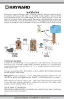
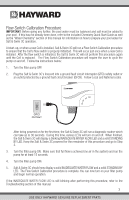
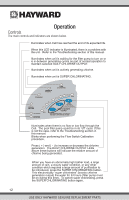
Flow Switch Calibration Procedure IMPORTANT: Before going any further, the pool water must be balanced and salt must be added to your pool. If this has not already been done, refer to the included Chemistry Quick Start Guide as well as the "Water Chemistry" section of this manual for information on how to prepare your pool water for Salt & Swim 3C operation. At start-up, or when a new Cell is installed, Salt & Swim 3C will run a Flow Switch Calibration procedure to ensure that the Cell's flow switch is properly initialized. This will occur just once when a new Cell is installed. After the flow switch is initialized, the Salt & Swim 3C will not perform this procedure again until the Cell is replaced. The Flow Switch Calibration procedure will require the user to cycle the pump on and off. Follow the instructions below: 1. Turn the filter pump OFF. 2. Plug the Salt & Swim 3C's linecord into a ground fault circuit interrupter (GFCI) safety outlet or an outlet protected by a ground fault circuit breaker (GFCB). Follow Local and National codes. GFCI OUTLET After being powered on for the first time, the Salt & Swim 3C will run a diagnostic routine which can take up to 30 seconds. During this time, various LEDs will turn on and off. When finished, the Salt & Swim 3C will display a blinking INADEQUATE WATER FLOW LED and a solid STANDING BY LED. Keep the Salt & Swim 3C powered for the remainder of this procedure and go to Step 3. 3. Turn the filter pump ON. Make sure that full flow is achieved (no air in the system) and run the pump for at least 15 seconds. 4. Turn the filter pump OFF. 5. Salt & Swim 3C should now display a solid INADEQUATE WATER FLOW and a solid STANDING BY LED. The Flow Switch Calibration procedure is complete. You can now turn on your filter pump and begin normal operation. If the INADEQUATE WATER FLOW LED is still blinking after performing this procedure, refer to the Troubleshooting section of this manual. 7 USE ONLY HAYWARD GENUINE REPLACEMENT PARTS
-
 1
1 -
2
-
3
-
 4
4 -
 5
5 -
 6
6 -
 7
7 -
 8
8 -
 9
9 -
 10
10 -
 11
11 -
 12
12 -
 13
13 -
 14
14 -
15
-
16
-
17
-
18
-
19
-
20
-
21
-
22
-
23
-
24
 |
 |